Tags
Electronics production
- Eagle : Export PCBs quickly with this script
- Grow monitors | What watches the watchers?
- Networking light : Twin PCB
- Phototransistor breakout board
- EAGLE pt2 : Fabricating the circuit board
- Fabricating, wiring, learning
- LCD ATTiny44 PCB
- EAGLE pt1 : Designing a circuit board
- Stuffing a circuit board
- Milling a circuit board
2017 May 01
#electronics
#cut2d
#elecFab
In a previous project based on an ATtiny44 I added an expansion pin on PA2 (ADC2/AIN1/PCINT2). I think I can use that pin to take readings from a phototransistor; making this a nice little project to get generate some momentum. Remember: spiral development.
First I examined Neil Gershenfeld's ATtiny45 schematic, the ATtiny45 datasheet, the ATtiny44 datasheet, andthe OP580DA phototransistor datasheet.
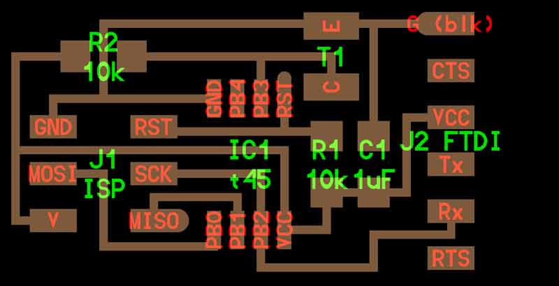


Because both pins are compatible with Analog to Digital Conversion (ADC), the phototransistor should work with my ATtiny44 board. The first step is to design a board for the phototransistor, resistor, voltage, ground, and logic connections. I use Autodesk's Eagle.
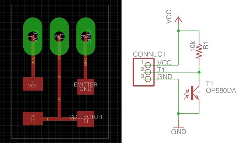
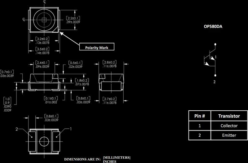
Relatively simple schematic. One thing to be aware. The phototransistor is directional. You can check the datasheet for that. Hint the chamferred corner aligns with the collector side.
Out comes the traces and interior (linked below for download).
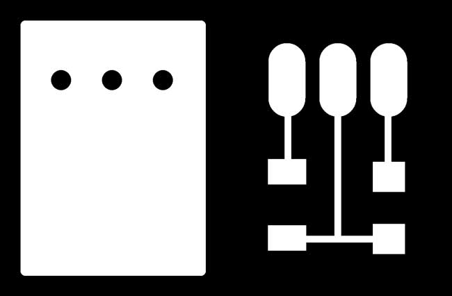
A quick milling job.
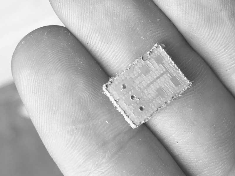
Cleaned up and stuffed.
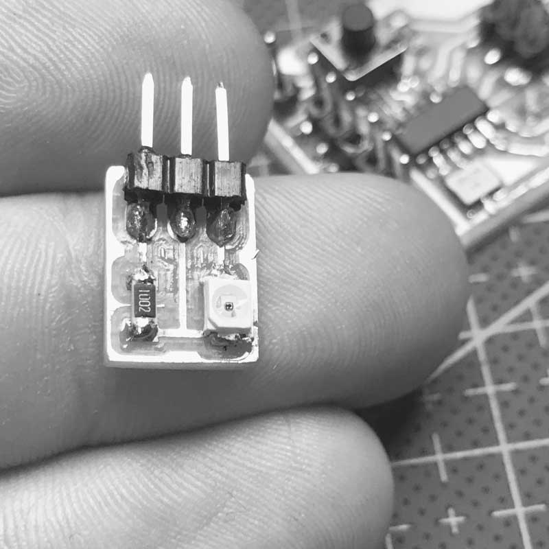
Want to make one? You can do that.
Download project files
Share this post...
« Previous post :: Liquid plastic : Smooth-Cast 300 Series
The first substance I attempted to cast was Smooth-Cast 300 Series, a liquid plastic with a curing time of just 10 minutes. Here is an overview from the datasheet: "The Smooth-Cast® 300 Series of liquid plastics are ultra-low viscosity casting resins that yield castings that are bright white and virtually bubble free. Vacuum degassing is not necessary. They o er the convenience of a 1A:1B by volume or 100A:90B by weight mix ratio. The di erences between them are pot life and demold time. These resins readily accept llers (such as URE-FIL® 3 from Smooth-On) and can be colored with...
Next post :: Phototransistor : reading »
I will try a variety of programming languages until I get readings. I am pulling VCC and Ground connections from the ISP so my order of operations: program with my fabISP, disconnect fabISP and connect phototransistor VCC and GND. That looks like this. I thought this might be simple... I first tried this Arduino sketch for getting readings via the serial monitor. Unfortunately, I am not yet able to get any reading from the serial monitor, let alone light levels. // Using an ATTiny44 #include <SoftwareSerial.h> SoftwareSerial mySerial = SoftwareSerial (1,0); // RX PA1 12, TX PA0 13 // Pin...