2017 May 24
#coding
#electronics
#appCode
In graduate school, I had the fortune of learning a bit of Processing, which I used in an interactive design project called FIZZLE in Hollywood. That was then, this is now. Now is a time when I have forgotten everything. Until today. From the processing website:
"Processing is a simple programming environment that was created to make it easier to develop visually oriented applications with an emphasis on animation and providing users with instant feedback through interaction. The developers wanted a means to “sketch” ideas in code. As its capabilities have expanded over the past decade, Processing has come to be used for more advanced production-level work in addition to its sketching role. Originally built as a domain-specific extension to Java targeted towards artists and designers, Processing has evolved into a full-blown design and prototyping tool used for large-scale installation work, motion graphics, and complex data visualization."
First thing, it is a good idea to download Processing.
I started with the Getting Started page on the Processing website. You can do that too. I do not know if it is the clear similarities between the Processing Development Environment (PDE) and Arduino IDE or a flood of old memories returning, but this feels very familiar. Like an old blanket. In this sketch, void setup runs once and void draw loops infinitely.
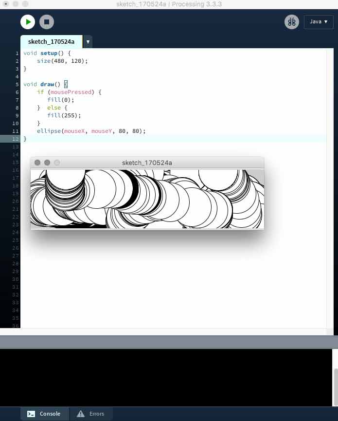
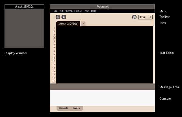
Here is a nice graphic from the website explaning the interface.
After a few minutes of following through the tutorials linked above and below, I decided to just jump in. Enough with the tutorials. Tutorials have their place, but how many different ways do I really need to draw a circle right now? I want to get this connected with my boards!
I found some FabAcademy geared Processing example sketches here. I decided I would start trying to make an animated graphic that reads my phototransistor. I thought that would be easy. Little did I know...
I edited a previous Arduino sketch for greater simplicity. This sends data from the phototransistor to serial for interacting with Processing.
// Using an ATTiny44
// The most basic reading of the phototransistor output to serial
#include <SoftwareSerial.h>
SoftwareSerial mySerial = SoftwareSerial (0,1);    // RX PA1 12, TX PA0 13

// Pin Configurations
const int sensorPin = A2;  // PA2
const int LED = A7;        // PA7
int sensorValue = 0;       // variable to store the value coming from the sensor
//int outputValue = 0;        // variable to store the PWM


void setup() {
// declare the LED as an OUTPUT:
pinMode(LED, OUTPUT);
mySerial.begin(19200);   // I set this to 19200 and arduino monitor to 2400
mySerial.println("Start.");
}

void loop() {                   // read the value from the sensor every 50 ms
sensorValue = analogRead(sensorPin);
mySerial.println(sensorValue);  // print reading to Serial
//outputValue = map(sensorValue, 0, 1023, 100, 0);  //0 is dark, 100 is bright
//mySerial.println(outputValue);  // print converted reading to Serial
//digitalWrite(LED, HIGH);      // Blink LED for visualizing sensor timing
delay(50);    // calibrate for stability in readings
//digitalWrite(LED, LOW);
//delay(50);
}
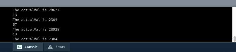
First problem, the Processing serial monitor was incompatible with my board. I was getting erratic readings, irregardless of anything, ie, disconnecting the phototransistor from my board. Something like this:
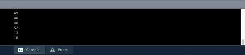
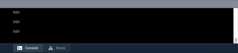
When it should have been this:
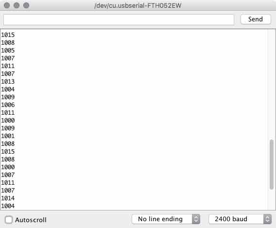
Immediately, my mind went back to the timing problems I have had over and over and over again with these ATtiny 44 boards. What am I missing here? I searched around, rolling it back to the start and I found I never used Burn Bootloader. All this time.
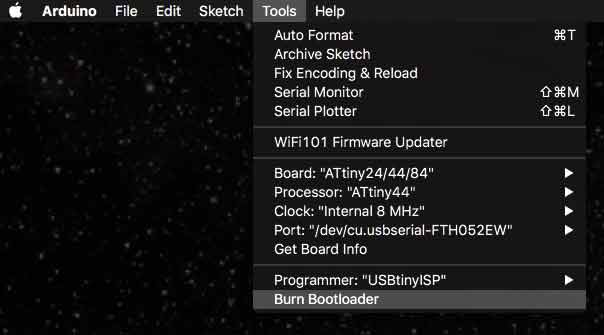
After doing that step, the timing and serial BAUD rate issues melted into distant memories of resilient night terrors. One thing though, the external clock Bootloaders are not working. I will come back to this another day. I think, the resonator is a tough piece to solder, I have already decided to increase the pad lengths next time I use it. I will test this on other boards I have with similar setups and diagnose after that. For now, I am using the 8mHz internal clock.
Still using an example code from the bottom of this page which is a processing conversion of Neil Gershenfeld's python phototransistor reading script, my processing readings did not match the Arduino serial readings.
I stripped the sketch down to its most essential elements for transimitting information from serial and still did not have parity with Arduino.
import processing.serial.*;

Serial myPort;  // Create object from Serial class
int val;      // Data received from the serial port

void setup()
{
size(200, 200);
// I checked the port list in the Arduino menu, first Bluetooth... then FTDI
String portName = Serial.list()[1];
myPort = new Serial(this, portName, 9600);  // I set code to 19200 and monitor to 2400
}

void draw()
{
if (myPort.available() > 0) {    // If data is available
val = myPort.read();           // read it and store it in val
println(val);
}
}
Finally, on the Sparkfun tutorial data is read from serial and stored in a String, instead of an int.
import processing.serial.*;

Serial myPort;  // create an object from Serial class
String val;      // data received from the serial port

void setup() {
String portName = Serial.list()[1];
myPort = new Serial(this, portName, 9600);
}

void draw() {
if ( myPort.available() > 0) {
val = myPort.readStringUntil('\n');
}
println(val);
}
Boss.
A string is a sequence of characters though. This may be a problem. Now I am having some fun with tutorials, so I continue with the next communicating from Processing through my board, to Arduino and back to the board. First the processing sketch. When I perform a mouse click within the processing menue, a 1 is written via serial.
import processing.serial.*;

Serial myPort;  // create an object from Serial class
String val;      // data received from the serial port

void setup() {
size(200,200);  // draw a window 200x200 pixels
String portName = Serial.list()[1];  //adjust for your FTDI cable
myPort = new Serial(this, portName, 9600);  //match arduino
}

void draw() {
if (mousePressed == true) {
myPort.write('1');
println("1");
} else {
myPort.write('0');
}
//if ( myPort.available() > 0) {
//val = myPort.readStringUntil('\n');
//}
println(val);
}
Arduino recognizes that and illuminates the LED. And it works.
#include <SoftwareSerial.h>
SoftwareSerial mySerial = SoftwareSerial (0,1);    // RX PA1 12, TX PA0 13

char val;  // Data from serial
int ledPin = A7;

void setup() {
pinMode(ledPin, OUTPUT);
mySerial.begin(9600);
}

void loop() {
if (mySerial.available())
{ // If data is available to read,
val = mySerial.read(); // read it and store it in val
}
if (val == '1')
{ // If 1 was received
digitalWrite(ledPin, HIGH); // turn the LED on
} else {
digitalWrite(ledPin, LOW); // otherwise turn it off
}
delay(10); // Wait 10 milliseconds for next reading
}
I want to communicate both ways. Apparently, this is called a handshake. Again, following the guiding hand of the tutorial. The Arduino adds a boolean function for controlling the LED and setups an additional loop to confirm communication with Processing through the board. When there is no communication from Processing, it asks for some.
#include <SoftwareSerial.h>
SoftwareSerial mySerial = SoftwareSerial (0,1);    // RX PA1 12, TX PA0 13

char val;  // Data from serial
int ledPin = A7;  //ATtiny44
boolean ledState = LOW; //toggle the LED

void setup() {
pinMode(ledPin, OUTPUT);
mySerial.begin(9600);
establishContact();  // send a byte to establish contact until receiver responds
}

void loop() {
if (mySerial.available() >0 ) { // If data is available to read,
val = mySerial.read(); // read it and store it in val

if (val == '1') { // If 1 was received
 ledState = !ledState;  //flip the boolean
 digitalWrite(ledPin, ledState); // turn the LED on
}
delay(100);
} else {
mySerial.println("Feed me, Seymour!");  //send back demand for food
delay(50); // Wait 10 milliseconds for next reading
}
}

void establishContact() {
while (mySerial.available() <= 0) {
mySerial.println("A");  //send A
delay(300);   // adjust delay for stability
}
}
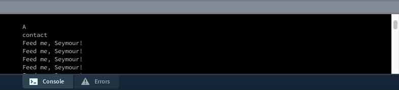
Processing adds and if / else statment within a serialEvent void for confirming contact (based on a new first contact boolean and listening for an "A" from Arduino). Arduino knows there is contact when it receives any kind of meesage through serial. Then, Processing prints whatever is communicating over the serial port and in case of a mouse press, sends a 1. When Arduino sees the 1, it flips the ledState boolean LOW/ HIGH. If you disconnect Processing and try to reconnect, the board needs to be reset because the first establishContact has already taken place on one side while the processing side will wait forever.
import processing.serial.*;

Serial myPort;  // create an object from Serial class
String val;      // data received from the serial port
boolean firstContact = false;  //check if MCU is communicating

void setup() {
size(200,200);  // draw a window 200x200 pixels
String portName = Serial.list()[1];  //adjust for your FTDI cable
myPort = new Serial(this, portName, 9600);  //match arduino
myPort.bufferUntil('\n'); //'\n is carriage return (new line - end of packet)
}

void draw() {

}

void serialEvent( Serial myPort) {  //put the incoming data into a String -
val = myPort.readStringUntil('\n');
if (val != null) {  //make sure our data isn't empty before continuing
val = trim(val);  //trim whitespace and formatting characters (like carriage return)
println(val);
if (firstContact == false) {
if (val.equals("A")) {  //look for 'A' string to start the handshake
  myPort.clear();   //if it's there, clear the buffer, and send a request for data
  firstContact = true;
  myPort.write("A");
  println("contact");
}
}  else { //if we've already established contact, keep getting and parsing data
println(val);
if (mousePressed == true) {    //if mouse click in window
myPort.write('1');        //send a 1
println("1");
}
myPort.write("A");  // when you've parsed the data you have, ask for more:
}
}
}
Download project files
I will post links to resources I have found helpful here.
Share this post...
« Previous post :: Testing the electrical components of the IR network twins
Infrared light is invisible to the human eye, so it is a challenge to know if the infrared LED is operational. Further, the sensors need to be operationally tested. I setup some simple arduino sketches to confirm the board. First, you need to match the ATtiny44 pins to Arduino speak. Look at this graphic and compare it to the schematic. The LED is on ATtiny 12, irLED 11 and irSensor 10. One, two, three. I will add those as integars. Now, many cameras can see infared light. The front camera on newer iPhones is one such camera. const int irPin...
Next post :: Processing Light Graph »
Enough with the tutorials. Now I would like to start putting these together with some kind of simple visual or audio interface connected to sensor readings. I started by looking at this former Fab Academy student's work mapping phototransistor settings to a dynamically configurable 3D model. He was able to combine sensor readings from arduino with a Processing sketch from Open Processing Org, a wonderful place for sharing processing sketches. I went there with the intention to grab a sketch, however I was a little overwhelmed so instead I started looking at former Fab Academy students' pages for a sketch...