Tags
Wild Cardboard
Background
Amongst us there exists a typology of machines that can transfer code from a computer, often sent through a standard print dialogue, into a series of two-dimensional cutting pathes for cutting and engraving a number of materials from wood, leather and cardboard to metals, glass and plastics (and the machines precisions are measured in micrometers and do their work fast!). What if you had access to these machines? What would you create? What will I do?

wildCardboard posts...
- Wild Cardboard : Fabbing, Branching, Versioning | 2017 Feb 15 | 9 minute read
- Grasshopper Parametric Modeling | 2017 Feb 15 | 8 minute read
- Kerf : what is it? why is it? why care? | 2017 Feb 11 | 4 minute read
- Darth Cthulhu, tempting the darkside with lasers | 2017 Feb 11 | 2 minute read
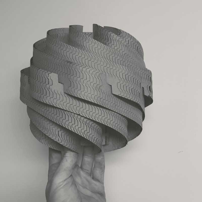
Now the real adventure begins. In a perfect world this would fit together on the first cut. I am going to assume it is not a perfect world and rely on the flexibility of my parametric model to adjust to the imperfections. The first big challenge will probably be successfully bending, or maybe not. I do not have prior experience with kerf pattern flexure joints. If I clear the bending hurdle, the center joints along the ribbons will probably be tricky because I am having to make an assumption on how this will behave prior to building the model. Testing...
I decided to try learning the Rhinoceros parametric GUI plugin Grasshopper for the cutting prototype. The Grasshopper project's aim is to make programming easier to understand through an intuitive visualization. The GUI looks similar to Antimony with a model window and a graph window. Scripting nodes in Python, C#.net and VB.net is also possible. Grasshopper is available with Rhinoceros on MacOS and Windows. Launch Rhinoceros. Enter "grasshopper" in the command line. The Grasshopper interface will launch. Across the top are several tabs which contain links to "objects" which are scripts of varying complexity. The primary section of the screen is...
A laser beam is generated in the back of the machine and reflected through a series of mirrors, through a focusing lens then the material. The narrowest part of the beam, around an 0.32mm diameter, is aligned to the material (z-axis). The head of the machine moves along X and Y axes across a cutting bed directing the laser through the designated cuts. The intensity, speed, and pulses per inch (ppi) are user defined variables, in my case defined first by line color in the design software and second via a dialogue in the machine settings. These variables will effect...
For fun to practice with adjusting and experimenting with settings, I decided to make an engraving on my notebook. I happened to have a Darth Vader - Cthulhu (maybe my two favorite things?) portmanteau on my desktop... In photoshop, I resized the image and converted it to a bitmap. Within the bitmap settings there are a number of different methods, each producing different pixelation effects. I wanted to make something expressive of vertical lines so I used the "Halftone Screen..." and after a few tests, came to 10 Lines/cm, 90 degrees (vertical) angle and the "Line" shape. I also found...