Tags
Wild Cardboard
2017 Feb 11
#cut2d
#wildCardboard
#CCC
A laser beam is generated in the back of the machine and reflected through a series of mirrors, through a focusing lens then the material. The narrowest part of the beam, around an 0.32mm diameter, is aligned to the material (z-axis). The head of the machine moves along X and Y axes across a cutting bed directing the laser through the designated cuts. The intensity, speed, and pulses per inch (ppi) are user defined variables, in my case defined first by line color in the design software and second via a dialogue in the machine settings. These variables will effect how deeply the laser penetrates the material, if completely, then the amount of edge burn or melt. The resulting gap from a slit is known as the kerf. Kerf width will be effected by the user defined variables and with some careful setup can be minimized. Kerf can be tested and measured then translated into corresponding parametrics in your computer models.
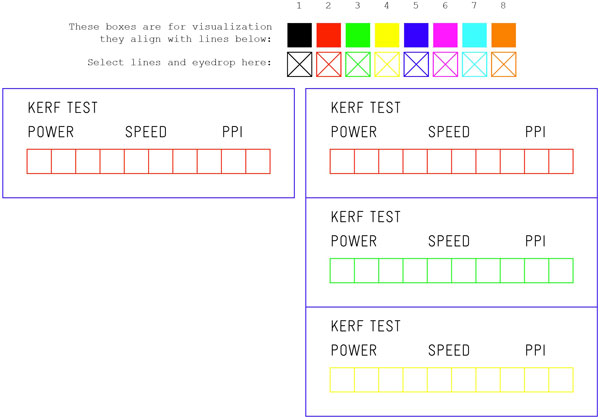
One easy way to measure kerf is to use the kerf test file I have provided. Load the file into your laser cutter, and be sure to carefully calibrate the black lines (notes) for engraving and the series of squares to the desired test cut variables. Line width may be dependent on laser cutter model, in my case: 0.01mm (the line width in the image below is adjusted for visibility). The file also includes color calibrated linetypes that can be cloned to lines within any drawing.
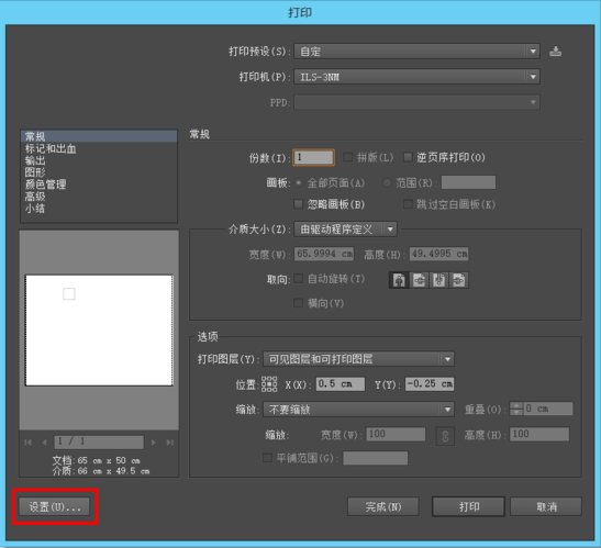
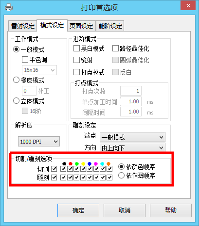
Okay, this part is tough because I cannot read most Chinese pictographs. There are four basic steps.
- Press print and then bypass the application specific print dialogue, if existing.
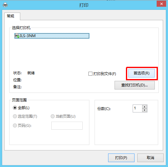
- Select the laser cutter and choose settings.
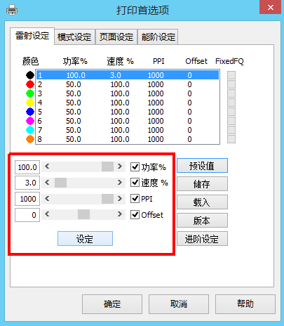
- Adjust the user defined variables for each color used in the drawing. Only these exact colors will be recognized by the cutter. In the files I provided, the colors are calibrated. The first setting is power. The second speed. The third PPI.
- Notify the cutter which colors will be used for which efforts, the top row is cutting the bottom engraving. Engraving is performed first, cutting second. Within each set of operations, the order of the colors will be the sequence of operation (starting with black and ending with orange). Organize cuts with potential material movement in mind, ie cut from the micro to macro.
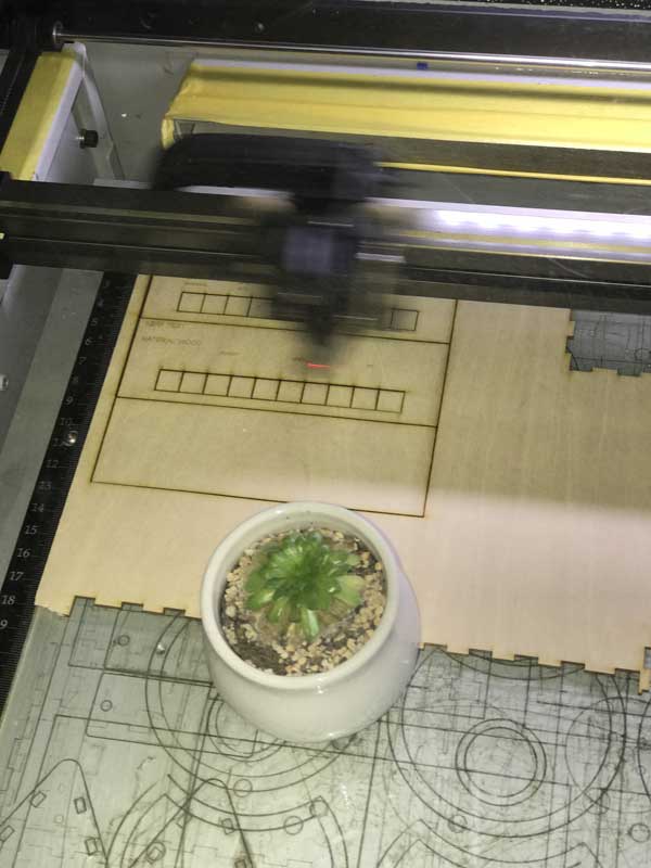
Now turn on the machine and the exhaust fan. Give a couple minutes to warm up the laser. While that is happening, load in the material. Align the material to the X,Y origin of the cutting bed. If there is warping in the material, tape or weight it down to get close to flat. Then position laser head near the center of the planned cutting area and align the bed height to the laser focal point, in our case 6mm. The arrow keys move on the XY plane, holding the fast key speeds up the movement. P1 is the final resting point of the laser head. P2 is near the XY origin. Up and down raise and lower the bed. This can be done with a designated piece of material by carefully raising the bed while constantly checking the gap between the material and laser head. When raising the bed, do not leave the checker under the head because it will not be obvious when the head is touching.
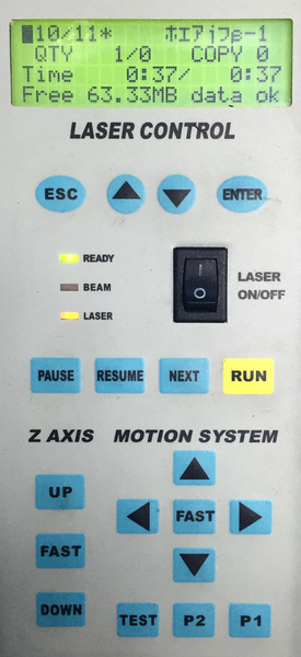
Now its ready. Select your file from the onboard queue using the next button. Finally, press Run and watch the magic. Do watch the magic. Do not leave the machine while it is cutting or you will burn your lab to the ground. The pause button can buy you time for a biology break and resume button will do what it implies.
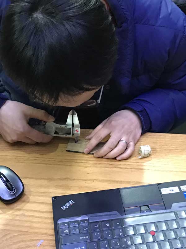
After the template is cut, align all the squares into the mold, push to one side and use calipers to measure the gap. Divide this measurement by 11 (number of vertical cuts) and you will have the average kerf for x material at abc variables.
I will post links to resources I have found helpful here.
- Single-line fonts link repository : Single-line fonts can speed up laser cutting by reducing the number of cuts. Most fonts are made of an outline with a fill. Essentially this is two mostly parallel lines. Single lines are one. Half the time. Magical.
Share this post...
« Previous post :: Darth Cthulhu, tempting the darkside with lasers
For fun to practice with adjusting and experimenting with settings, I decided to make an engraving on my notebook. I happened to have a Darth Vader - Cthulhu (maybe my two favorite things?) portmanteau on my desktop... In photoshop, I resized the image and converted it to a bitmap. Within the bitmap settings there are a number of different methods, each producing different pixelation effects. I wanted to make something expressive of vertical lines so I used the "Halftone Screen..." and after a few tests, came to 10 Lines/cm, 90 degrees (vertical) angle and the "Line" shape. I also found...
Next post :: Grasshopper Parametric Modeling »
I decided to try learning the Rhinoceros parametric GUI plugin Grasshopper for the cutting prototype. The Grasshopper project's aim is to make programming easier to understand through an intuitive visualization. The GUI looks similar to Antimony with a model window and a graph window. Scripting nodes in Python, C#.net and VB.net is also possible. Grasshopper is available with Rhinoceros on MacOS and Windows. Launch Rhinoceros. Enter "grasshopper" in the command line. The Grasshopper interface will launch. Across the top are several tabs which contain links to "objects" which are scripts of varying complexity. The primary section of the screen is...