2017 Feb 15
#model3d
#cut2d
#wildCardboard
#CCC
Now the real adventure begins. In a perfect world this would fit together on the first cut. I am going to assume it is not a perfect world and rely on the flexibility of my parametric model to adjust to the imperfections. The first big challenge will probably be successfully bending, or maybe not. I do not have prior experience with kerf pattern flexure joints. If I clear the bending hurdle, the center joints along the ribbons will probably be tricky because I am having to make an assumption on how this will behave prior to building the model. Testing it will require at least two ribbons and the four couplings, so I very well may end up with two or more wasted ribbons. Enough speculation. BUILD!
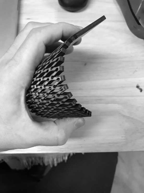
This is an example of kerf pattern flexure laser cut in 4mm thick wood. The vector file can be found here and an image of the cuts are further down this section. Without that pattern removed, I assure you this wood is stiff.
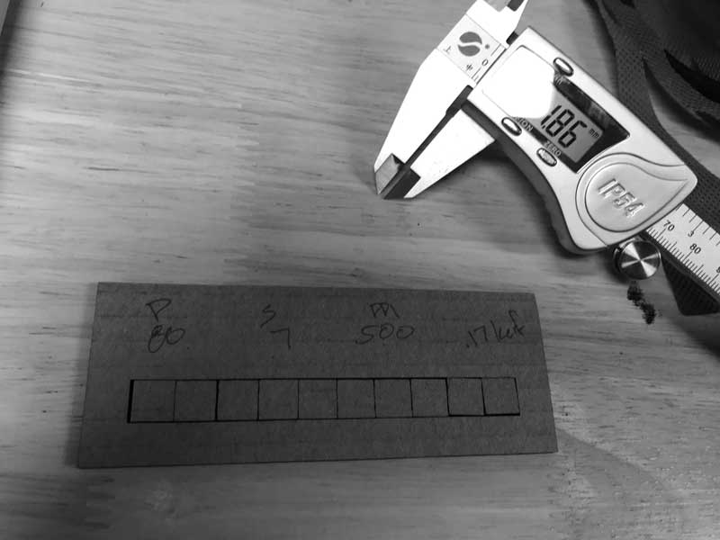
I rooted around the material closet and found some flattened cardboard boxes that should be good for prototyping this tricky press-fit kit. The first step is simple: measure for the cardboard thickness. Cardboard is easily smooshed in zones, especially the recycled stuff, so I took several measurements and averaged the thickness to be 3.00mm. This became the thickness variable in my grasshopper model.
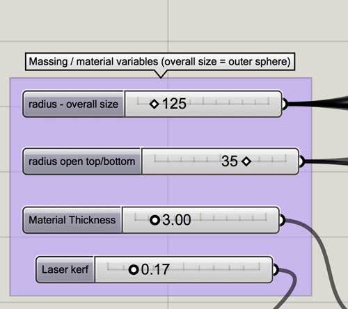
Unfortunately, the materials the lab have on hand are not as big as I was hoping. On one hand, I should have scouted more selectively from the beginning. On the other, I have a parametric model. Last night, I had set the variables to maximize the bed size of the laser cutter: 660mm x 495mm, however the cardboard I am using only measures 330mm x 430mm. I went to adjusting the variables to fit this new size restraint. I need to reduce the ribbons, reduce the overall size, reduce the sweep, and increase the ribbon height. Now I have a piece that fits the reduced outside dimensions of the material. I am concerned whether the bending will be achievable in the reduced radius with cardboard. Starting now, this build uses these variables:
top/bottom opening size : 35mm radius
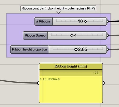
ribbon height proportion : 2.85
number of ribbons : 10
ribbon sweep : 4
material thickness : 3mm
laser kerf : 0.17mm (more on this next)
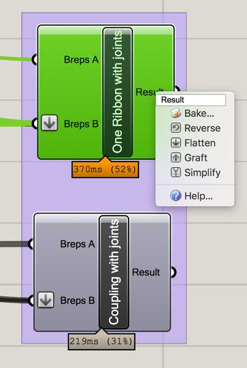
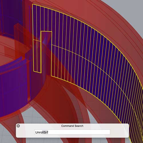
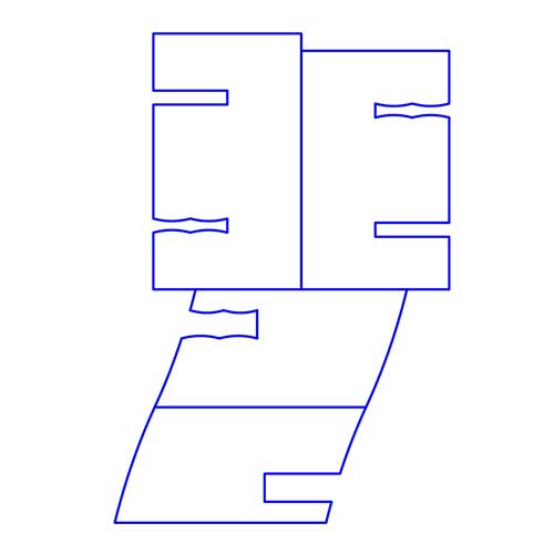
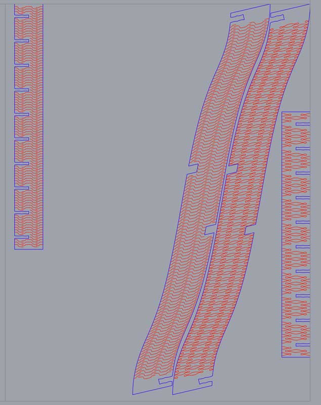
Now I do a kerf test. I found some tests around the lab for 2mm cardboard and 4mm cardboard and I went by feel somewhere between those numbers. 80 Power, 7 Speed, 500 PPI. My results were .17mm kerf on this cardboard. Tight. Moving on. I inputted the laser kerf variable. The model thickness will slightly compensate for the kerfing: 3.00 - 0.17/2 = 2.91mm. Now that all the user values are in grasshopper, it is time to kick out the three components. The Bake command imports components from a grasshopper node into the rhinoceros modeling space, it also breaks the history on that piece, unless it is relinked back into grasshopper. These nodes export polysurfaces. Explode them. Then unroll the inside side face of the polysurface. Extract wireframe. Do some minor CAD adjustments. In the current grasshopper graph, the joint depth is double. I have a way to fix this and it will be in the uploaded model files.
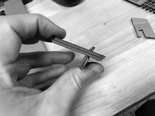
I have the three components more or less prepared. It is a good time to test the joint sizes grasshopper is outputting. I setup a small test for two joints typologies. One with two arcs and the other simply straight lines. The size is correct, however the straight line joint is loose whereas the double arc joint is very tight. I have some concern with how this joint may work when the material is bending. Although, I am using the inside surfaces to set the curvature, so the joint should open slightly if anything. Right? After the bend test, I will reassess. I will get to that in the next test.
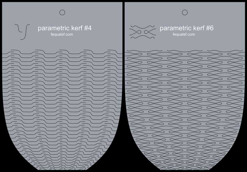
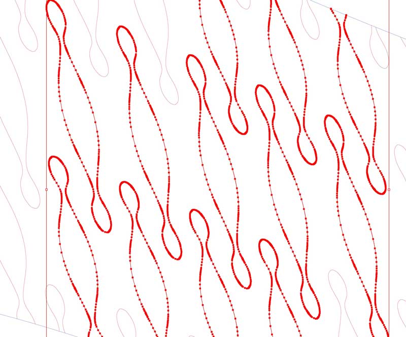
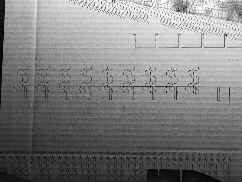
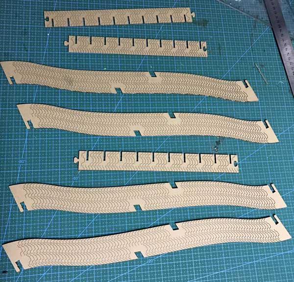
Testing kerf patterns. Ideally, this would be incorporated into the grasshopper graph. This minute, it is not. Old school, slow school method. I used the flow onto surface command to wrap the kerf patterns to the unrolled ribbons with some careful modifications of scale, spacing and edge conditions around the joints. These modifications should ensure the components are healthy and also made my shy away from spending hours trying to perfect a grasshopper graph to do the job automatically. Not that I mind spending the hours learning because that should save me hours later. This moment time is short. The flow along surface keeps the kerfing perpendicular to the bending direction. I apply the kerf pattern to one of the couplings. If it works on one, it will work on both. I chose two open source patterns for this prototype to get experience and save time: one pattern has many openings and more flexibility, while the other no openings and less flexibility. I hope the latter can achieve the ribbon sweeps. The couplings are mostly hidden, either pattern, if effective, will be sufficient. For prototyping cardboard the kerf pattern flexure is fine. However, if I were to develop this project further, I think I would opt for an opaque material with enough flexibility to achieve my desired bending. That would likely look better in this design. Or, maybe not. Seeing is knowing.
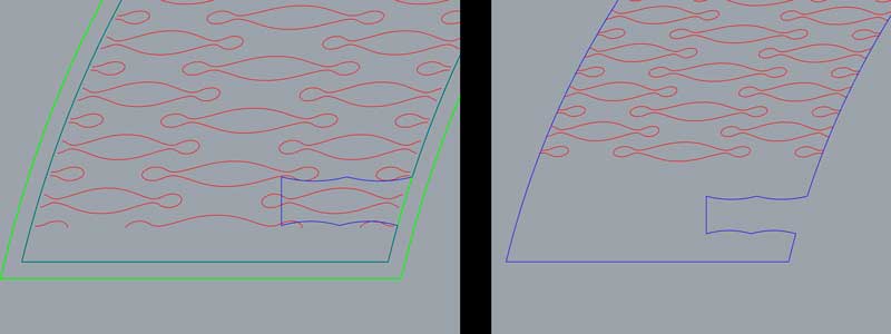
I had a problem with the flow along surface command. The pattern was not properly intersecting with the boundary curves. Time for a little hacking, I offset the boundary curves on both the source and target surface, re-project the pattern, flow again between the increased-size surfaces, then project the now adequately sized pattern onto the originally intended surface and clean up around the joints.
Two pairs of pieces are prepared for the bending test. Due to constraints on the cardboard size, I’m testing this cut at an angle not at all related to the corrugation. It may be necessary to bend along the corrugation but I will have to make the already small model, smaller still (the short side is perpindicular to the corrugation). Will the kerf pattern be effective in spite of the corrugation...?
Shit! The laser cutter and its companion computer stopped communicating with one another. Perfect timing. I reset both systems and checked all the connections. Scrolled through some menus on the Windows machine and the LCD display based settings of the laser cutter and could not solve the lack of communication. That was a question I would have loved to learn tonight, maybe even to finish the model. Alas, I have to wait until tomorrow moring.
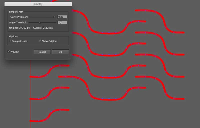
The problem with the laser cutter was user error. User error is the worst kind of problem, especially when it takes almost 18 hours to solve. Eighteen precious hours… In Rhinoceros, when I flowed the kerf pattern onto my component pattern, the vector complexity increased about tenfold. Each vector increased from around 14 to over 150 control points by hundreds of kerf vectors. Illustrator was jamming the laser cut queue trying to communicate the file and I was too impatient. Throwing fuel on the fire, the connected computer’s graphic cards keeps getting overloaded and crashing the system.
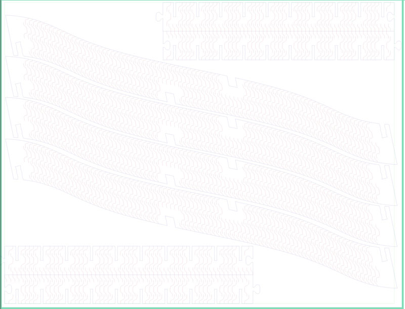
The vectors can be simplified in Illustrator or Rhinoceros. I tried both. I think illustrator does a better job because ux dictates curviness desire whereas the rhinoceros options are more fickle. Really, both work well. I just prefer Illustrator. If the kerf pattern were incorporated in my grasshopper graph, I would probably address the point density problem there instead of Illustrator, for instance. This image shows the power of Illustrator to reduce the points even further than what I managed in Rhinoceros. Keep in mind, the precision of these kerf curves is not critical, as long as the deviation is not great.
The first bend test was the version with the squiggly holes. The cardboard bends quite easily. In fact, the ribbon is probably too flexible. I do not know if I can achieve much springiness in cardboard with kerf bending. The second pattern does achieve more springiness. I decided to reduce the number of cuts because it is still too flexible and I will get the added bonus of speeding up the job. Another potential problem spot was around each of the two middle joints of the ribbon, the cardboard is too weak and easily folds.
One other interesting thing started happening where the laser cutter offset paths of different colors in weird ways. After two jobs, it seems to have stopped doing it.
After I believed I had fixed all the quirks, I prepared to begin cutting the final components of this prototype.
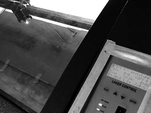
The kerf adds TIME. And I mean TIME! One sheet: four/ten ribbons, three/four couplings. That requires around 75 minutes of machine time. Fortunately, all the cuts were perfect.
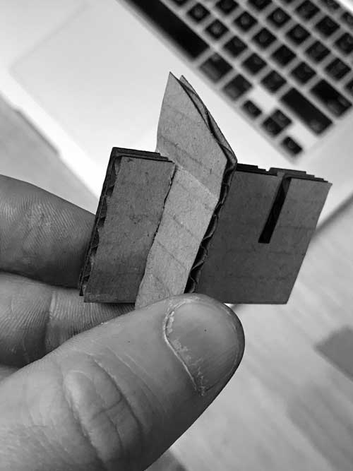
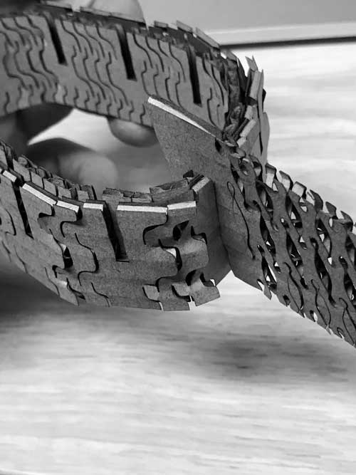
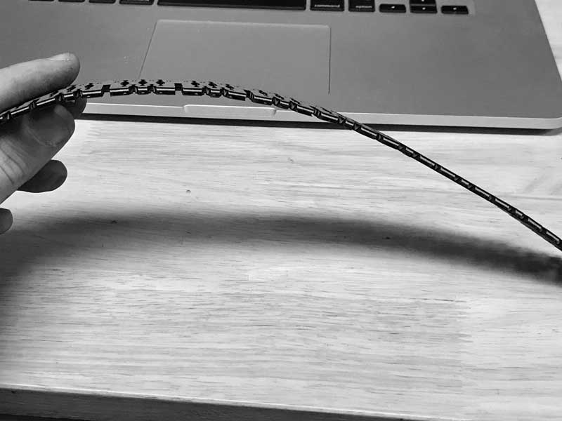
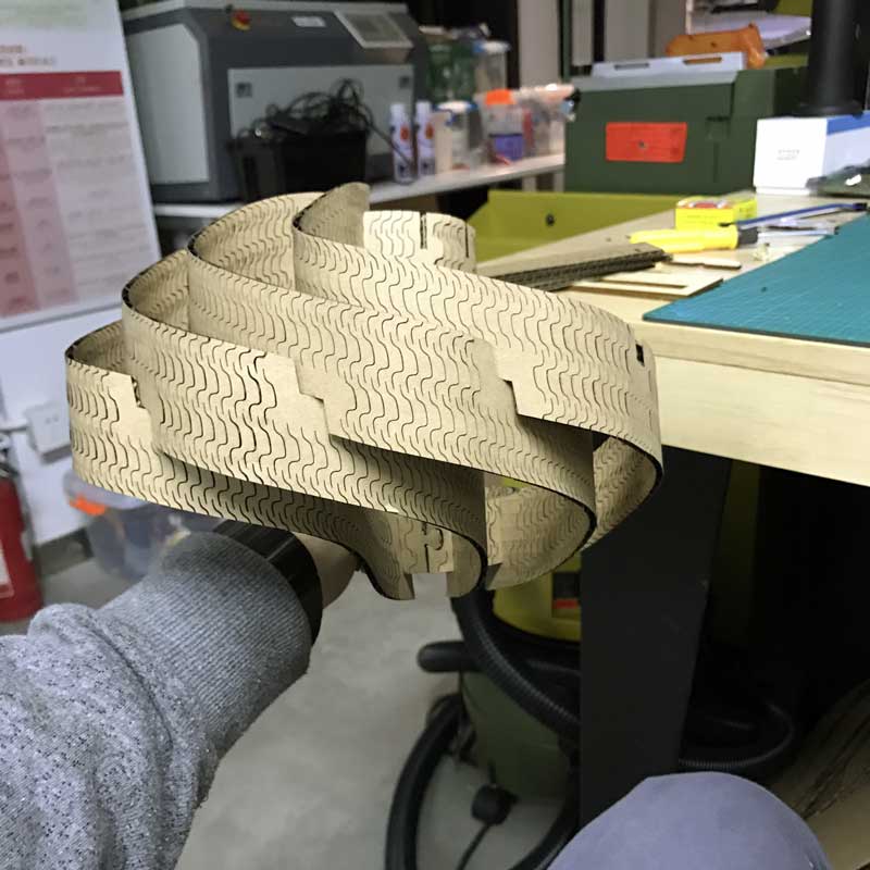
While the second sheet was cutting I could not wait to start putting together my thing. A tip for the kerf, gently pull apart and bend throughout the length of the surface. That primes the component for curving and minimizes folding quite well. Right away, I was super pleased with how easy all the components lock together. There were some complex relationships in this thing due to its curv-tastic geometry. Yet, thus far, the 3D model and this laser cut version are spot on. I know that sometimes getting something like this to lock stitch together is often one of the toughest parts of the project. So, I would say I am yet cautiously optimistic. One slight problem that I noticed in the three-d model and forgot to change before fabrication is the thickness of the tail end of the ribbons just beyond the slot. That part probably should have been another 4mm plus / minus. Thus far though, with care because the joints are very tight, it has not been a problem and does not appear as if it will snap in this prototype. Assembly is a snap!
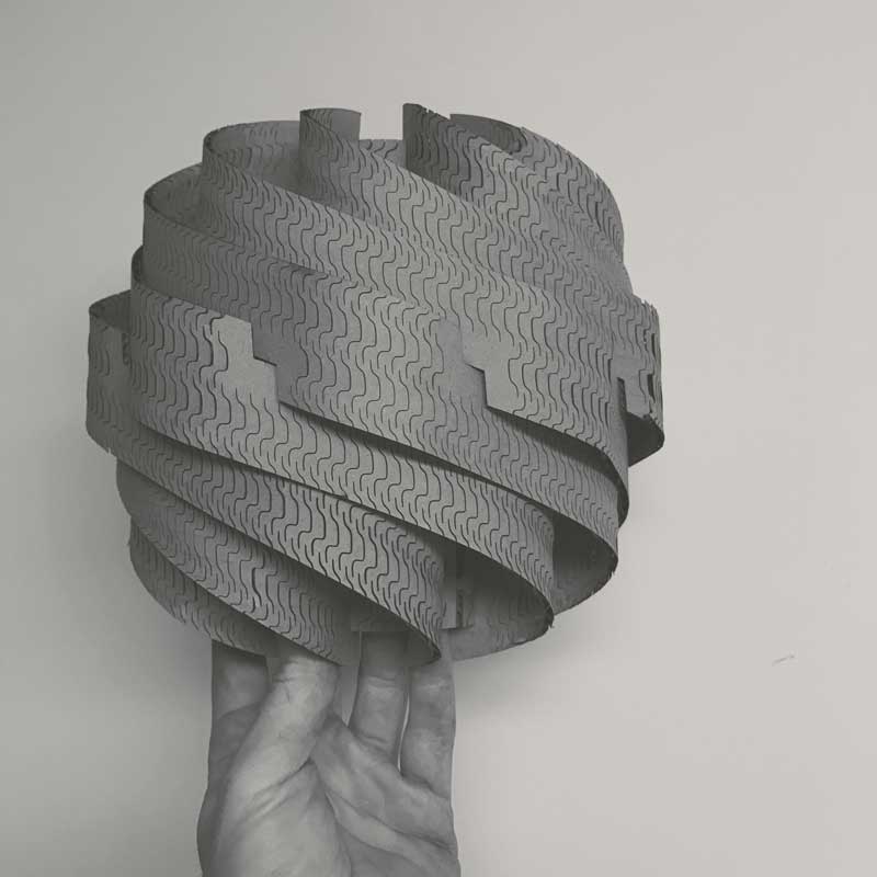
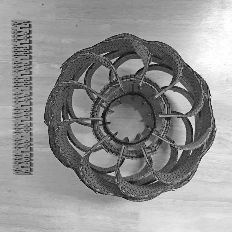
And it comes together! I should have built some scaffolding to hold the upper and lower couplings in spatial relation to one another. Or, had an extra pair of helping hands. It is really tricky to pull the last few pieces togehter because of the torque moving in opposite directions from top to middle to top. Some of the ribbons took damage in that final step. Fortunately, it did not explode, which seemed very likely at one point. I will return here in the next day or two and conclude the lessons and upload working files so... yes you can.
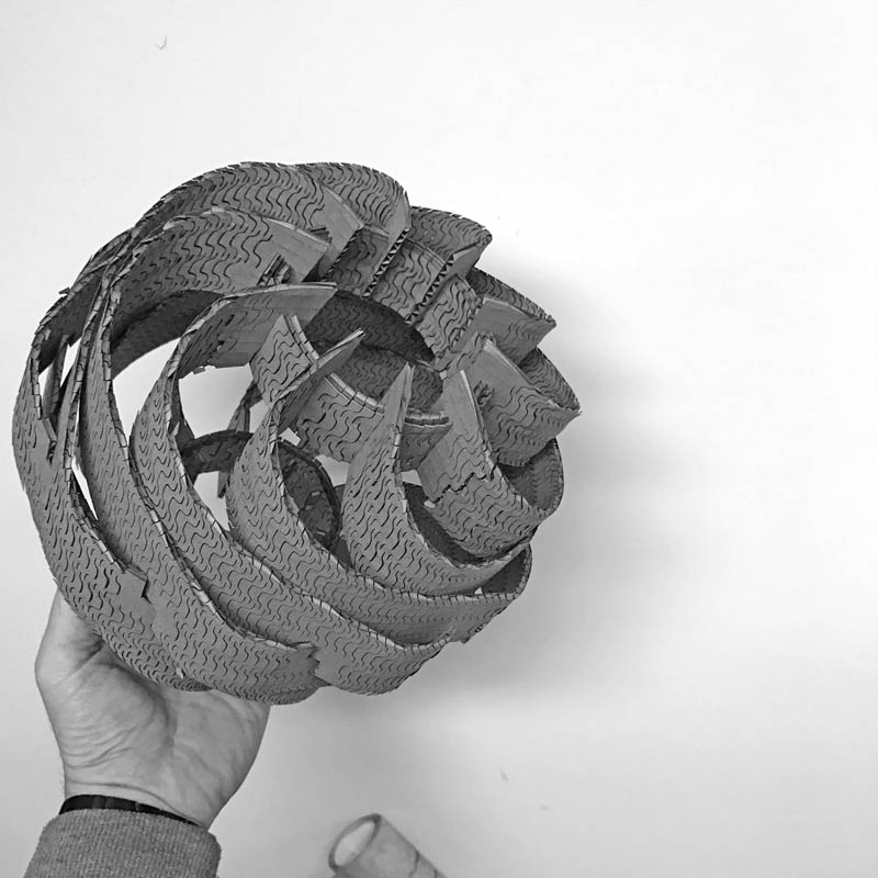
I came a long way in just a few days. That is what makes these processes special. From a first time build in grasshopper, to rapid prototyping, to holding a working version in my hand (made from cardboard of all materials). Feels fantastic. I will sleep well tonight. Then tomorrow, get started on making an in-circuit programmer by milling the PCB.
I will post links to resources I have found helpful here.
- Core77 kerf bending survey : This post gives a good overview of the technique.
- Aaron Porterfield Instructables beginning kerf bending : This post includes downloadable files and comparisons of different techniques' effectivenss.
- Aaron Porterfield Instructables advanced kerf bending : Explorations in variable kerf densities through parametric modeling (grasshopper). Variation is set via curvature analysis. Working files posted for free use.
- Double curvature kerf pattern : A post describing process and downloadable files.
- Lattice Hinge Design — Minimum Bend Radius : An introduction to the science of kerf bending.
- Introduction to the curvature of surfaces : Do you know about principal, mean and gaussian curvature? You can..
- Variation from Uniformity : Perhaps this is a little off course in relation to this post. An introduction to the problem of limiting panel types in construction of doubly curved surfaces.
Share this post...
« Previous post :: Vinyl cutting, introduction
To test the vinyl cutter, I prepared a bēstia logo in Adobe Illustrator. I converted the graphic into a composition of vector shapes using the live paint tool. Now: cut time. First load the material into the machine. Release the clamp in the back. Align the sheet to the far left, parallel to one of the vertical lines along the front of the machine, and position the wheels to the furthest edges of the paper within the white marked zones. Return the clamp lever to the pressed position and notify the machine material is loaded. In this case, I used...
Next post :: Milling a circuit board »
The PCB is composed of a thin layer of copper, measuring in just microns of thickness, laminated onto FR1, phenolic paper. The pattern of copper connects a series of electronic components with electricity. If any unintentional connections are made, the whole system may be fried. While in subsequent posts, I will explore designing the etching patterns, this time around, I am using an open-source project developed in the FabLab ecosystem: the FabTinyISP version of an AVR ISP programmer/board. You can download the same PNG files I used for the traces and the board outline and read detailed build instruction on...