Background
Amongst us there exists a typology of machines that can transfer code from a computer, often sent through a standard print dialogue, into a series of two-dimensional cutting pathes for cutting and engraving a number of materials from wood, leather and cardboard to metals, glass and plastics (and the machines precisions are measured in micrometers and do their work fast!). What if you had access to these machines? What would you create?

Computer controlled cutting posts...
- CNC milled wood frame | 2017 Jun 28 | 5 minute read
- Bio-electro-chemistry | 2017 May 03 | 3 minute read
- Wild Cardboard : Fabbing, Branching, Versioning | 2017 Feb 15 | 9 minute read
- Vinyl cutting, introduction | 2017 Feb 15 | 3 minute read
- Kerf : what is it? why is it? why care? | 2017 Feb 11 | 4 minute read
- Darth Cthulhu, tempting the darkside with lasers | 2017 Feb 11 | 2 minute read
I would like to use 2 dimensional milling to cut a wood frame to carry the concrete grow modules and hide the electronics. There will be a small cut-out on one side for an LCD which will be displaying data coming from sensors across the system. The concrete casting process was not precise due to some flexure in the walls of the mold. Each module has an extra 4-5mm total width in both directions. So the first part of making the frame was to compensate for this error. I should note, I kind of like the little bit of error...
The fabrication demands of this project are far less than other aspects. Keep it simple. Spiral develop. I essentially want an open-faced cube in acrylic. I will develop a grasshopper, parametric model with variables for overall dimensions, finger joint size, laser kerf, bolt and other holes (unrelated to box adhesion). The prototype is based on the work of Paolo Bombelli, et al. This is the desired composition. The pot, plastic fixture and possibly rubber washers will be laser cut and Jakob Skote's Moss Powered Wifi Jammer project. Excellent work. Visit them. Fast-forward a little in time and I have a...
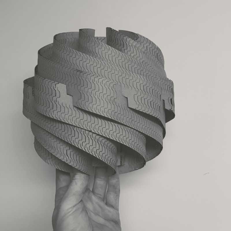
Now the real adventure begins. In a perfect world this would fit together on the first cut. I am going to assume it is not a perfect world and rely on the flexibility of my parametric model to adjust to the imperfections. The first big challenge will probably be successfully bending, or maybe not. I do not have prior experience with kerf pattern flexure joints. If I clear the bending hurdle, the center joints along the ribbons will probably be tricky because I am having to make an assumption on how this will behave prior to building the model. Testing...
To test the vinyl cutter, I prepared a bēstia logo in Adobe Illustrator. I converted the graphic into a composition of vector shapes using the live paint tool. Now: cut time. First load the material into the machine. Release the clamp in the back. Align the sheet to the far left, parallel to one of the vertical lines along the front of the machine, and position the wheels to the furthest edges of the paper within the white marked zones. Return the clamp lever to the pressed position and notify the machine material is loaded. In this case, I used...
A laser beam is generated in the back of the machine and reflected through a series of mirrors, through a focusing lens then the material. The narrowest part of the beam, around an 0.32mm diameter, is aligned to the material (z-axis). The head of the machine moves along X and Y axes across a cutting bed directing the laser through the designated cuts. The intensity, speed, and pulses per inch (ppi) are user defined variables, in my case defined first by line color in the design software and second via a dialogue in the machine settings. These variables will effect...
For fun to practice with adjusting and experimenting with settings, I decided to make an engraving on my notebook. I happened to have a Darth Vader - Cthulhu (maybe my two favorite things?) portmanteau on my desktop... In photoshop, I resized the image and converted it to a bitmap. Within the bitmap settings there are a number of different methods, each producing different pixelation effects. I wanted to make something expressive of vertical lines so I used the "Halftone Screen..." and after a few tests, came to 10 Lines/cm, 90 degrees (vertical) angle and the "Line" shape. I also found...