Tags
#cut2d
#model3d
#pureImagination
#CCC
Pure Imagination
- Environmental monitoring with online data logging to Thingsv
- Inventory
- Hessian/ burlap/ crocus composites
- CNC milled wood frame
- Grow monitors | What watches the watchers?
- Grow module | Design and fabrication
- Grow Module | The science
- Processing Light Graph
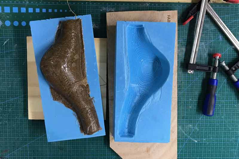
- Milling a composite mold
- Composites : Modular growth, testing
- Bio-electro-chemistry
- Bioelectrochemical testing pod
- LCD x Arduino
- Precedents
- Discussion
- Design, Materials and Methods
- History : Early concepts
2017 Jun 28
#cut2d
#model3d
#pureImagination
#CCC
I would like to use 2 dimensional milling to cut a wood frame to carry the concrete grow modules and hide the electronics. There will be a small cut-out on one side for an LCD which will be displaying data coming from sensors across the system.
The concrete casting process was not precise due to some flexure in the walls of the mold. Each module has an extra 4-5mm total width in both directions. So the first part of making the frame was to compensate for this error. I should note, I kind of like the little bit of error in the concrete, I think it gives the modules a little character and it is the reason I did not seek to reinforce the walls of the mold.
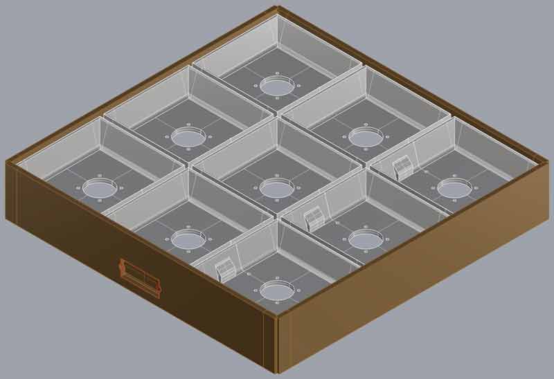
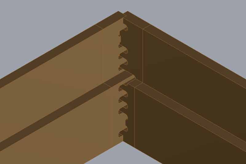
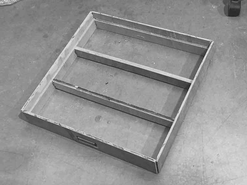
There are two types of joints, both of which I want to keep hidden. The rails catch a groove I designed into the base of the modules and there is not a crossing piece because of space required for electrical wires. I hope it is rigid without the opposite direction of ribs. The overall size is 484mm x 484mm.
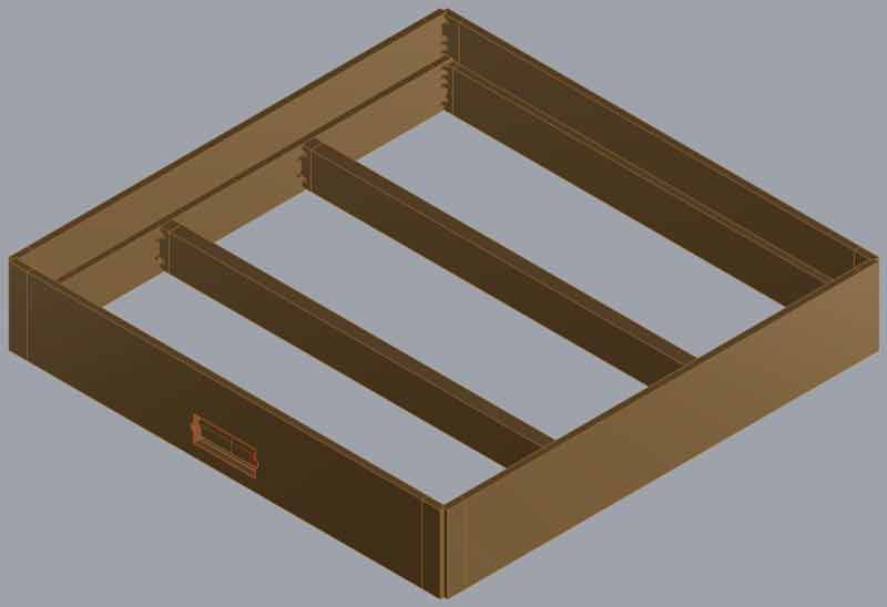
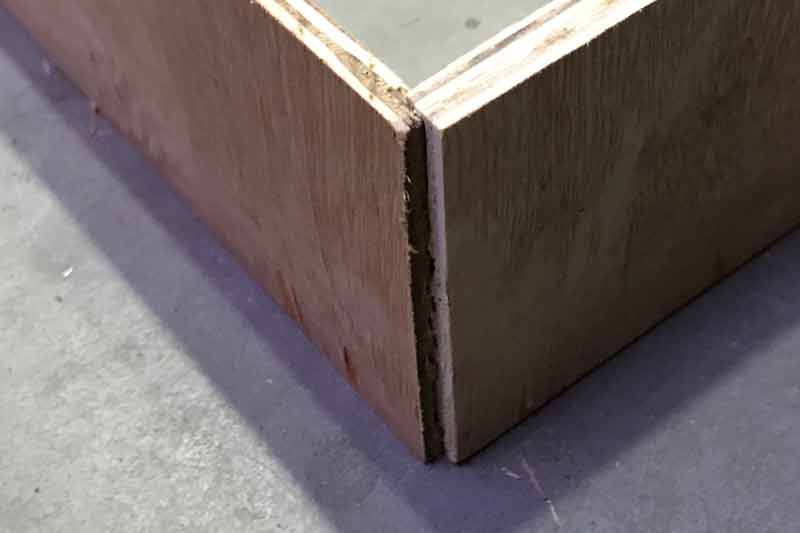
For the joints, I modified Secret Finger Tenons for the corners and the T joints were Throughole Finger Tenons. The graphic came from this ITP Fabrication post.
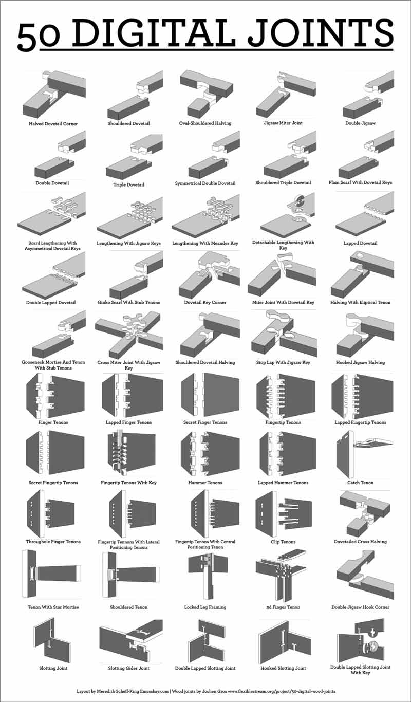
I redrew these joints for my plywood thickness: 14mm overall, 7mm in the upper half. From the outside, these will be invisible.
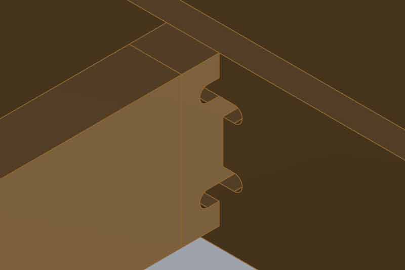
The T-joint was simplified for a smaller adjoining section of material and so that it does not go through the depth of the stock (invisible on the opposite side).
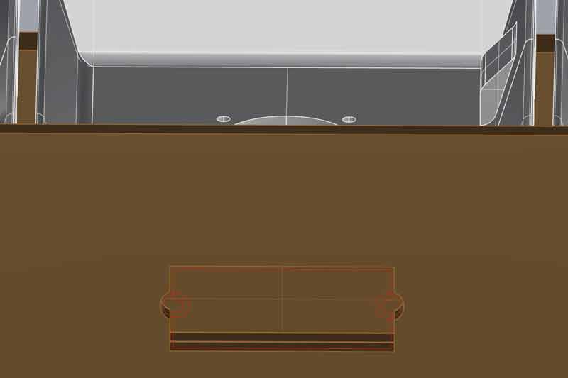
On the flipside of one of the outer pieces of frame, I will cut a pocket for a Lumex LCD module.
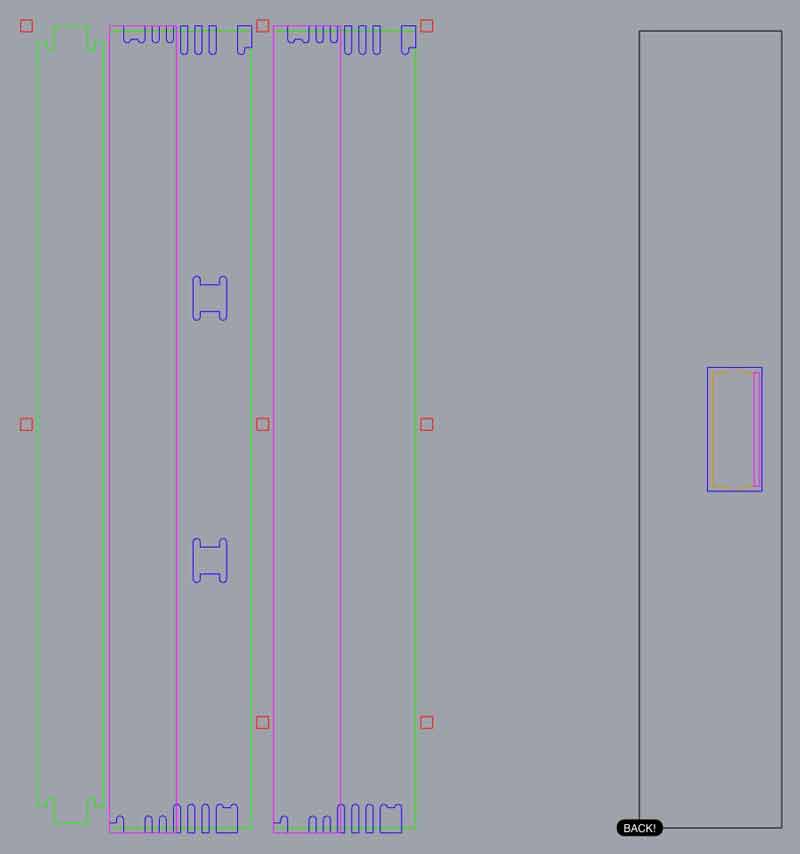
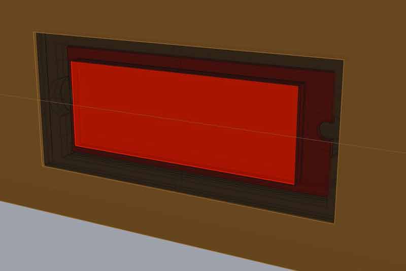
These are the cut lines. The Purple rectangles are 7mm pockets. The Blue zones are 10mm pockets. The green lines cut all the way through. And, the first job will be the red circles, just barely cut into the material in order to mark safe locations to screw the stock to the table. The blue and green lines need to be cut with a 4mm or smaller endmill. (The black circles are some existing holes in my plywood I want to avoid.)
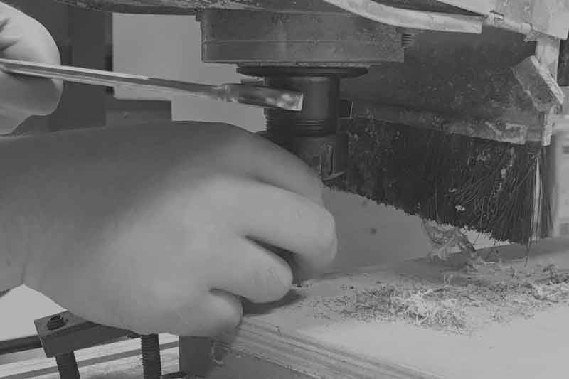
First I cut the slight pockets to mark the safe screw hole locations. This way, I ensured the stock was tight to the table around the toolpaths, which vary in depth. No toolpaths should go through the stock unless intended.
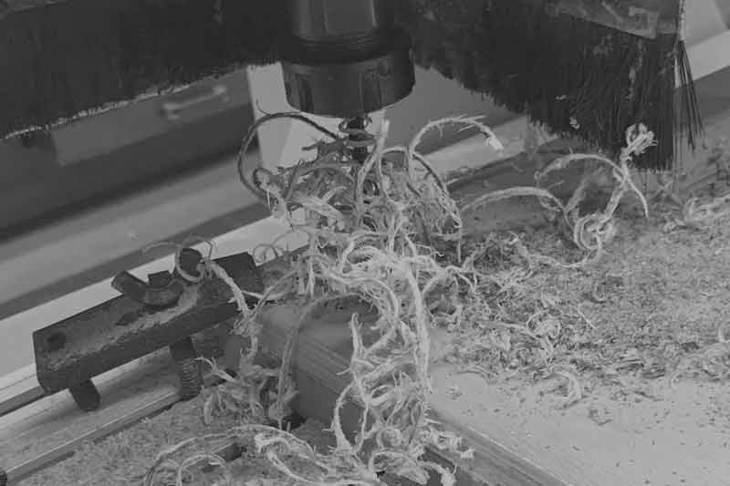
Be careful to check the tool often for too much cut material.
After cutting the pockets for the upper half of the walls, I switched from a 6mm to 3.165mm endmill.
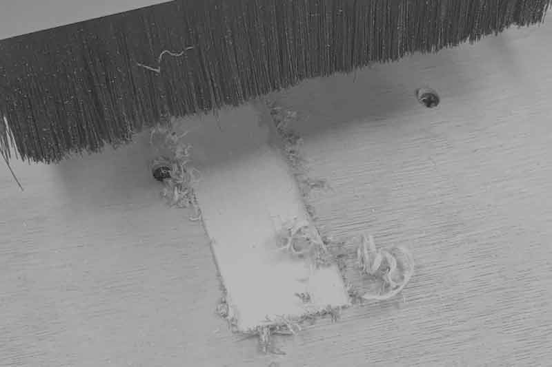
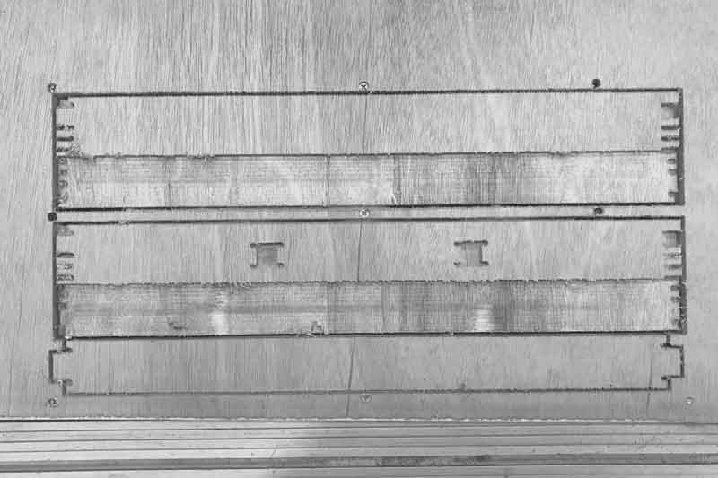
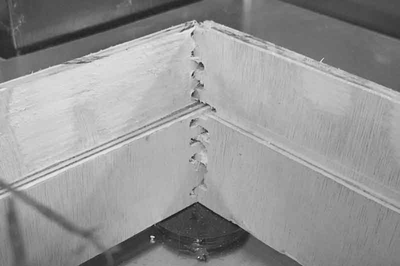
The third cut was the pockets for the connections between pieces and finally the outlines. I added 10mm x 5mm dogbones every 300mm which worked very well to keep the pieces together throughout the cut. After, it was not difficult to remove the three pieces.
All the joints worked as designed and the cuts went much better than my first try on this machine. I intentfully left extra space on the back side of the joints just to be certain the connections would work fully on the first try.
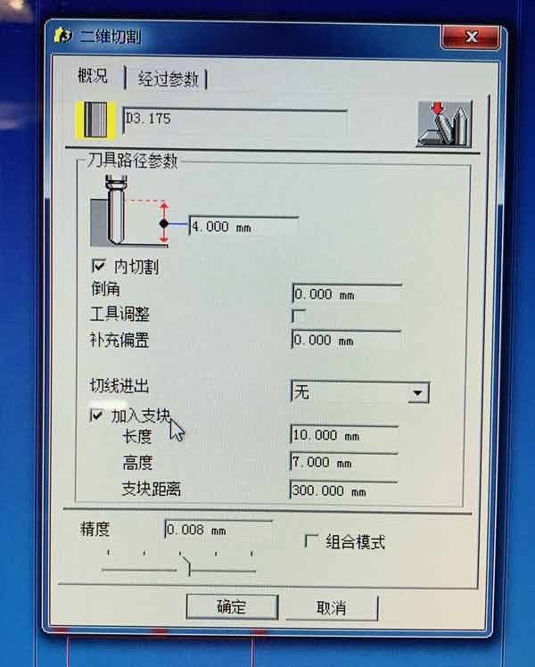
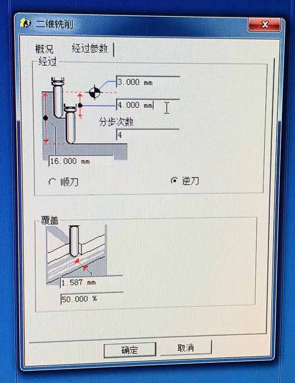
In Type3, this setting is used to make dogbones. The first of the three options is width, followed by height and finally distance between each. Bear in mind, the second setting is the total planned cutting depth plus dogbone height. For instance, -16mm cutting depth plus 7mm dogbone means -11mm to the top of the dobbone. This may be a factor if the total cutting depth is set slightly below the material thickness.
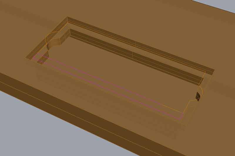
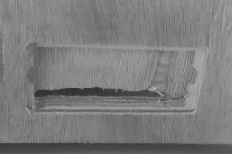
Next I flipped the wall without joints for the ribs and cut an pocket for a Lumex LCD. I added a little extra depth across the front so I can add a small laser cut piece of trim to conceal the circuit board behind the screen.
When I tested the LCD panel, I found the 1x pin header I soldered to the back of it was every so slightly throwing off the rotation of the LCD. With a dremel, I roughly fixed the wire opening. Looks like crap but will never be seen by anyone beyond this blog.
After this success, I cut three more identical pieces with the same gCode files for the other half of the box (no additional LCD).
After day one, I started looking through the gCode and found that some of the heights in the pockets were off by +3mm. When I returned to the lab, I found a setting in the Type3 software that was causing the problem. The zRef was set to 3mm. All my cutting depths were set to my depth input plus 3mm. Instead of using another 8 hours to recut all the pieces, I carefully used a dremel with an endmill and custom jig to fix the problems on the first three pieces I cut. The second three I fixed in the code before cutting.
The movement speeds in this lab are set from the terminal and password protected. Personally, I find this approach cumbersome and leading to a lack of education about proper movement speeds for different types of cuts, materials, etc.
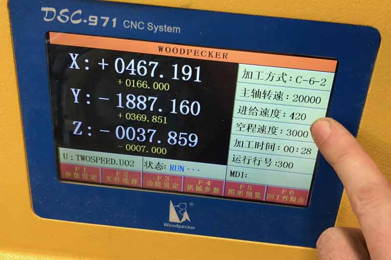
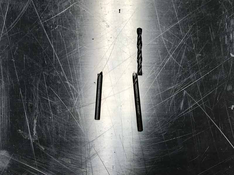
Perhaps related, two 3.165 end mills were broken. I cannot say if the setup of our job specifically caused this. At the time of both breaks the machine was cutting through 3mm depth plywood moving at 420mm per minute and for the other 300mm per minute.
Significant sanding was needed to clean up the wood at the cuts.
And, finally, the fully assembled plywood frame (no glue or fasteners). Empty it is very wobbly. Filled with the concrete grow modules, it stays true. Because the joints are hidden, they are not as strong as would be if they went all the way through the material. After building this, I would like to make adjustments and do a second version. However, using the CNC mill at Tongji is just too difficult and time consuming when working through language barriers with the lab technicians. However, it was a good experience in learning to overcome these barriers to entry to complete work. Next time I use a large format CNC machine, I hope it will be in my own language with me at the controls.
I will post links to resources I have found helpful here.
Share this post...
« Previous post :: Grow monitors | What watches the watchers?
Simultaneous to the module development, I will produce some grow module monitoring equipment. Previously, I worked with a phototransistor sensor, an LCD output and wrote a basic graphical interface for live monitoring the phototransistor readings. Today, my goal is to combine these with voltage sensoring so I can begin tracking the correlation between sunlight and power generation in the bioelectrochemical testing modules. Starting with a little research, I found that by simply connecting an input voltage to an open ADC pin, I could take voltage readings. Duh. I have been doing this for weeks via the phototransistor. I returned to...
Next post :: Hessian/ burlap/ crocus composites »
To make the composite surface, I will combine hessian with a two-part resin which takes about thirty minutes to set and five hours to cure. This job is messy business and I did not have gloves or time to get gloves. That was a bad idea, first, not many photos. Second, the resin gets very hot in just a few minutes, trial by fire. Finally, it is nearly impossible to get off your hands. After countless soapings, I resorted to scrubbing my hands with coarse hair brush/ soap combo and then wearing (different) gloves for the next few hours because...