Tags
#coding
#electronics
#pureImagination
#microCode
#elecFab
Pure Imagination
- Environmental monitoring with online data logging to Thingsv
- Inventory
- Hessian/ burlap/ crocus composites
- CNC milled wood frame
- Grow monitors | What watches the watchers?
- Grow module | Design and fabrication
- Grow Module | The science
- Processing Light Graph
- Milling a composite mold
- Composites : Modular growth, testing
- Bio-electro-chemistry
- Bioelectrochemical testing pod
- LCD x Arduino
- Precedents
- Discussion
- Design, Materials and Methods
- History : Early concepts
2017 Jun 14
#coding
#electronics
#pureImagination
#microCode
#elecFab
Simultaneous to the module development, I will produce some grow module monitoring equipment. Previously, I worked with a phototransistor sensor, an LCD output and wrote a basic graphical interface for live monitoring the phototransistor readings. Today, my goal is to combine these with voltage sensoring so I can begin tracking the correlation between sunlight and power generation in the bioelectrochemical testing modules.
Starting with a little research, I found that by simply connecting an input voltage to an open ADC pin, I could take voltage readings. Duh. I have been doing this for weeks via the phototransistor.
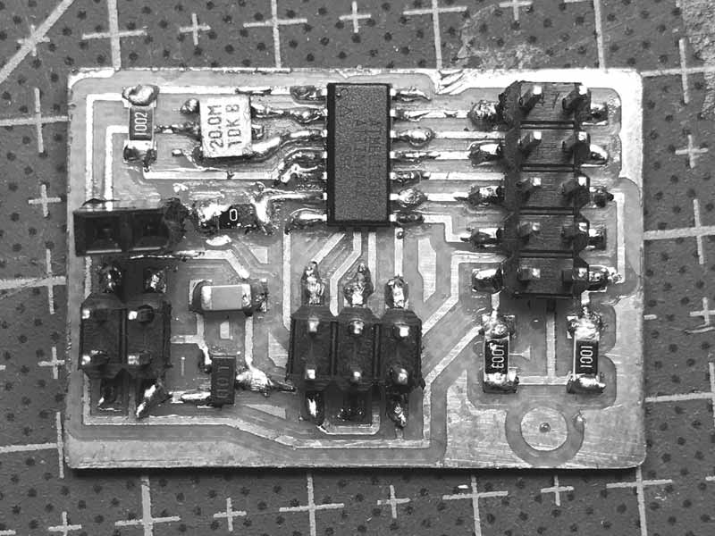
I returned to the LCD PCB I fabricated for an ATtiny 44 with an LED. The LED was connected to ADC7 of the ATtiny 44. Great news because I can quickly modify this board for testing voltage.
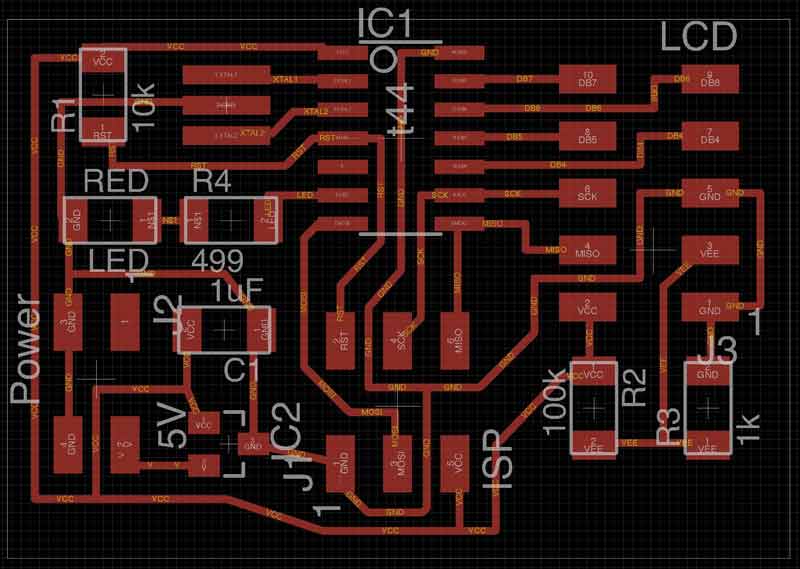
I never soldered the LED to the board. Instead, I soldered female pins, which is quite convenient now. I replaced the 499 resistor with a 0 ohm resistor at the electronics bench.
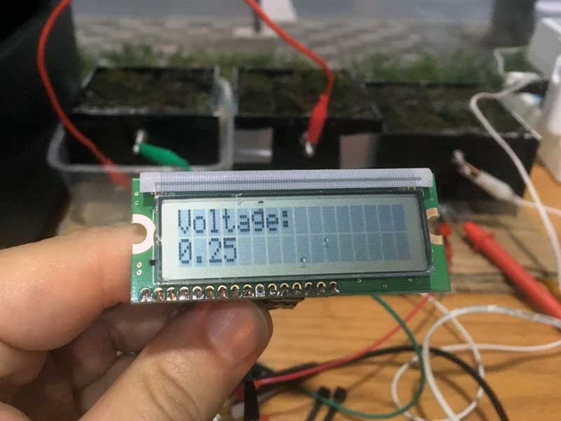
Then within Arduino IDE, I wrote this program. The floating number is necessary to get more precise readings, particularly with the small voltages coming from my current plant testing modules.
/*
J.travis russett presents
a simple programme to read up to 5 volts and print the results to an LCD
with an ATTiny 44.

The circuit:
  * LCD RS pin to digital pin 5
  * LCD Enable pin to digital pin 4
  * LCD DB4 pin to digital pin 3
  * LCD DB5 pin to digital pin 2
  * LCD DB6 pin to digital pin 1
  * LCD DB7 pin to digital pin 0

lcd(RS, E, DB4, DB5, DB6, DB7)
*/

#include <LiquidCrystal.h>

LiquidCrystal lcd(5, 4, 3, 2, 1, 0);

const int meterPin = 7;
int x;  //analogue pin reading
float y;  //converted to voltage

void setup() {
  //LCD stuff
  lcd.begin(16, 2);
  //Voltmeter stuff
  pinMode(meterPin, INPUT);
}

void loop() {
  int x = analogRead(meterPin); //Reads the analog value on pin A3 into x
  float y = (float)x * 5.000 / 1023.000; //convert analogue reading to Voltage
  lcd.clear();
  lcd.setCursor(0,0);
  lcd.print("Voltage: ");
  lcd.setCursor(0,1);
  lcd.print(y);
  delay(1000); //one second delay between readings, keep a small delay to compensate serial comm
}
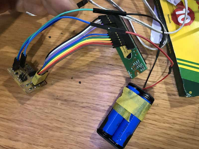
The cathode of the power source connects directly to the ATtiny pin and the ground is common to the board. I tested program with this pair of rechargeable batteries which may come into play at a later point to store energy produced by the plants.
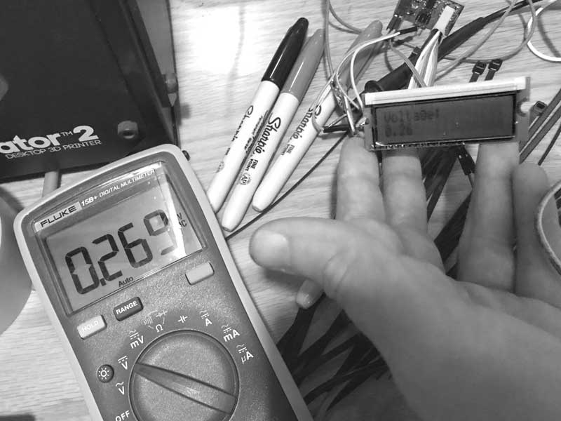
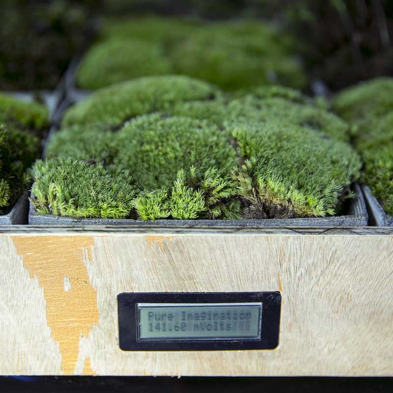
As my father loves to proclaim before a critical test, moment of truth. I connected the board to the plants (wired in series) and another volt meter as control. I like it.
And a much clearer picture from Fablab maestro, Saverio Silli:
I started working on checking the controller's internal volt reference but when I decided I would like to evolve to the ATmega, I set it aside and have not had a chance to resume yet. Because the readings from the controller are relative to the voltage coming in, and voltage can vary slightly from source to source, this is a way to calibrate analogue readings. As usual, it is in the datasheets.
#include <LiquidCrystal.h>

LiquidCrystal lcd(5, 4, 3, 2, 1, 0);

const int meterPin = 7;
int x;  //analogue pin reading
//float Vcc;  // 1.1V ADC Reference Voltage comparator
float y;  //converted to voltage

/* This doesn't work on an ATtiny44 right now
long readVcc() {
  long result;  // Read 1.1V reference against AVcc
  ADMUX = _BV(REFS0) | _BV(MUX3) | _BV(MUX2) | _BV(MUX1);
  delay(2); // Wait for Vref to settle
  ADCSRA |= _BV(ADSC); // Convert
  while (bit_is_set(ADCSRA,ADSC));
  result = ADCL;
  result |= ADCH<<8;
  result = 1125300L / result; // Back-calculate AVcc in mV
  return result;
}
*/

void setup() {
  //LCD stuff
  lcd.begin(16, 2);
  //Voltmeter stuff
  pinMode(meterPin, INPUT);
}

void loop() {
  //Vcc = readVcc()/1000.00;
  int x = analogRead(meterPin); //Reads the analog value on pin A3 into x
  float y = (float)x * 5.00 / 1024.000 * 1000; //convert analogue reading to Voltage
  lcd.clear();
  lcd.setCursor(0,0);
  lcd.print("Pure Imagination");
  lcd.setCursor(0,1);
  lcd.print(float(y));
  lcd.setCursor(7,1);
  lcd.print("mVolts");
  delay(5000);  //one second delay between readings, keep a small delay to compensate serial comm
}
Next, I went to work on a way to visualize and permanently log data from sensors with Processing. Much more detail on this can be found in my previous post on applications. First the Arduino code.
#include <SoftwareSerial.h>
SoftwareSerial mySerial = SoftwareSerial (0,1);    // RX PA1 12, TX PA0 13

const int meterPin = 7;
int x;  //analogue pin reading
//float Vcc;  // 1.1V ADC Reference Voltage comparator
float y;  //converted to voltage
int a;
int b = 0;

/*
long readVcc() {
  long result;  // Read 1.1V reference against AVcc
  ADMUX = _BV(REFS0) | _BV(MUX3) | _BV(MUX2) | _BV(MUX1);
  delay(2); // Wait for Vref to settle
  ADCSRA |= _BV(ADSC); // Convert
  while (bit_is_set(ADCSRA,ADSC));
  result = ADCL;
  result |= ADCH<<8;
  result = 1125300L / result; // Back-calculate AVcc in mV
  return result;
}
*/

void setup() {
  //LCD stuff
  //lcd.begin(16, 2);
  //Voltmeter stuff
  pinMode(meterPin, INPUT);
  //Serial stuff
  mySerial.begin(9600);
  establishContact();  // send a byte to establish contact until receiver responds
}

void establishContact() { //establish connection with processing
  while (mySerial.available() <= 0) {
  mySerial.println("A");  //send A
  delay(300);   // adjust delay for stability
}
}

void loop() {
  int a = mySerial.read();
  if (a == b) { // If data is available to read,
  //Vcc = readVcc()/1000.00;
  int x = analogRead(meterPin); //Reads the analog value on pin A3 into x
  float y = (float)x * 5.00 / 1024.000 * 1000; //convert analogue reading to Voltage
  //mySerial.print("mV = ");
  mySerial.println(y);  // print converted reading to Serial
  }
  else {
  delay(100);  //one second delay between readings, keep a small delay to compensate serial comm
}
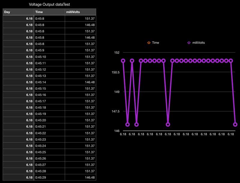
And the processing side is an evolution of my previous work. The biggest additions are corrections to the processing and arduino communication via serial, now Arduino properly awaits queries from processing, and Processing writes the data it receives with a time stamp to a text file in a format that can be simply copied and pasted into a spreadsheet application.
import processing.serial.*;

Serial myPort;   // create an object from Serial class
boolean firstContact = false;  //check if MCU is communicating
String val;      // data received from the serial port
float voltRead;      // converted string from serial port
color[] col = new color[1];
//int ax;
float xMax;    //tracking the highest value recorded
float xMin = 500;    //tracking the lowest value recorded
float xMinText;
float xMaxText;
PrintWriter output;

void setup() {
size(700, 300);
frameRate(40);
myPort = new Serial(this, "/dev/cu.usbserial-A402YTB1", 9600); ///dev/cu.usbserial-FTH052EW
initGraph();
output = createWriter( "voltage.txt" );
}

void serialEvent( Serial myPort) {  //put the incoming data into a String -
  val = myPort.readStringUntil('\n');
  if (val != null) {  //make sure our data isn't empty before continuing
  val = trim(val);  //trim whitespace and formatting characters (like carriage return)
  println(val);
  if (firstContact == false) {
    if (val.equals("A")) {  //look for 'A' string to start the handshake
      myPort.clear();   //if it's there, clear the buffer, and send a request for data
      firstContact = true;
      myPort.write("A");
      println("contact");
      delay(100);
    }
  }  else { //if we've already established contact, keep getting and parsing data
    String [] numbers = split(val, ',');
    float sensor[] = float(numbers);
    //println(sensor[0]);  //use to check processing reading data correctly
    voltRead = (float)sensor[0];

    output.print(month());
    output.print(".");
    output.print(day());
    output.print("\t");
    output.print(hour());
    output.print(":");
    output.print(minute());
    output.print(":");
    output.print(second());
    output.print("\t");

    output.println( voltRead );
    myPort.write(1);
    println(1);
    }
  }
}

void draw() {
  //[mostly] static elements
  background(255);
  fill(0);
  rect(100,100,500,100);  // (a, b, c, d) (x-coord, y-coord, width, height) x &y are upper left corner
  textSize(16);
  textAlign(RIGHT);
  text("mV", 75, 158);

  //[mostly]dynamic elements
  //int ax = round(x);
  textAlign(LEFT);
  text(voltRead, 625, 158);
  fill(col[0]);
  if (voltRead > xMax) {
    xMax = voltRead;
  }
  if (1< voltRead && voltRead < xMin) {
    xMin = voltRead;
  }
  rect(100, 100, voltRead, 100);
  line(xMin+100, 75, xMin+100, 225);
  line(xMax+100, 75, xMax+100, 225);
  int xMaxText = round(xMax);
  int xMinText = round(xMin);
  fill(0);
  textSize(12);
  textAlign(CENTER);
  text ("min", xMin+100, 250);
  text (xMinText, xMin+100, 264);
  text ("max", xMax+100, 58);
  text (xMaxText, xMax+100, 44);
  delay(950);  //adjust for desired frequency of readings
  myPort.write(0);
  println(0);
  delay(50);  //adjust for serial lag
}

void initGraph() {
  col[0] = color(31, 255, 194);  // R, G, B values
}

void keyPressed() {
  output.flush();  // Writes the remaining data to the file
  output.close();  // Finishes the file
  exit();  // Stops the program
}
And this is a test outputting to a spreadsheet. This is macOS numbers, which uses tabs to differentiate cell data.
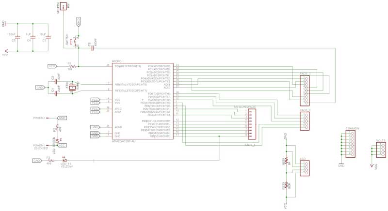
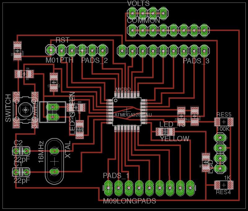
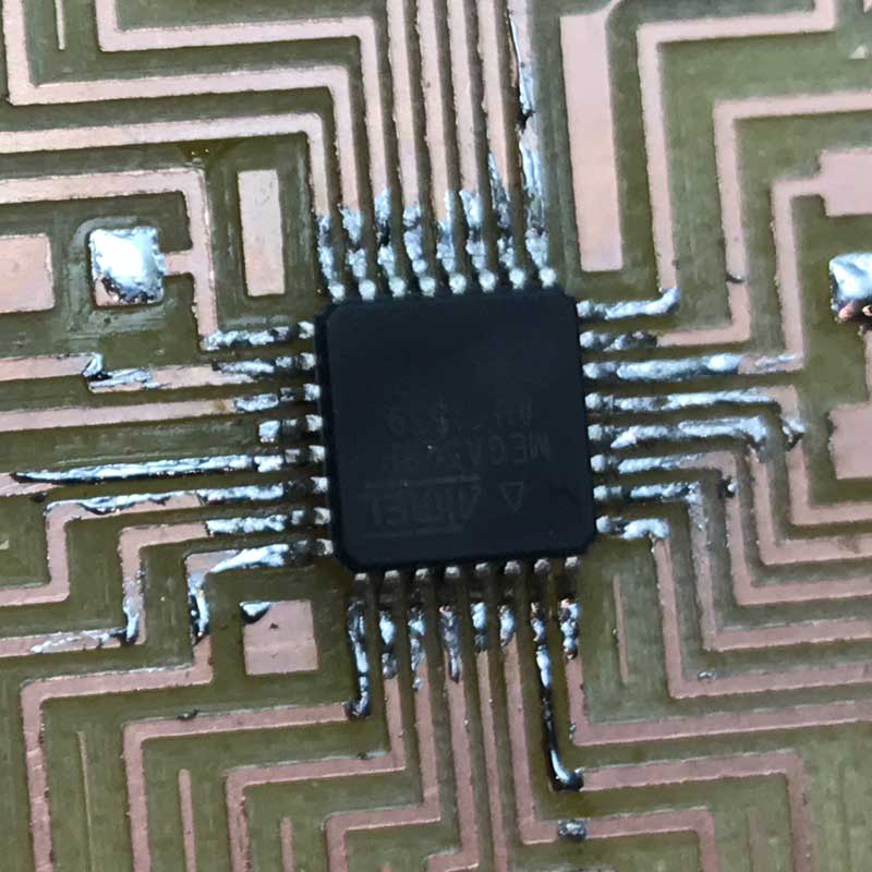
With some bits of code working and my ATtiny44 board maximized, I decided I would like a board that can output to serial and LCD, plus take readings from multiple module combinations or individuals and a variety of environmental sensors I found in the lab. That in mind, I thought I could upgrade to an ATmega board... for the first time in the Fab Academy cycle. Like many others, I started by studying then modifying Daniele Ingrassia's SatschaKit. I added many pins to be used for attaching breakout boards for environmental sensors and voltage readings plus resistors and additional pins for an LCD. After I fabricated it, I realized I should have added a regulator for voltage in from non-computer sources. I will do that and more in the next iteration.
In the meantime, I sourced an INA219 High-Side Current Monitor which work with I2C for current and voltage measurements. Plus I found this example uses Arduino IDE and ATMega I2C with an INA219 and an LCD output and by extension below, battery recharging management.
Soldering the ATmega is tough, especially if you do not have a sharp point on your soldering iron, like me. Instead, I applied small bits of solder to all the traces around the ATmega, carefully positioned it with the hot-air blower then slowly reflowed all the connections and added solder when needed. Jury is still out on whether that was effective, because I do not have the board running smoothly yet.
And the entire board stuffed:
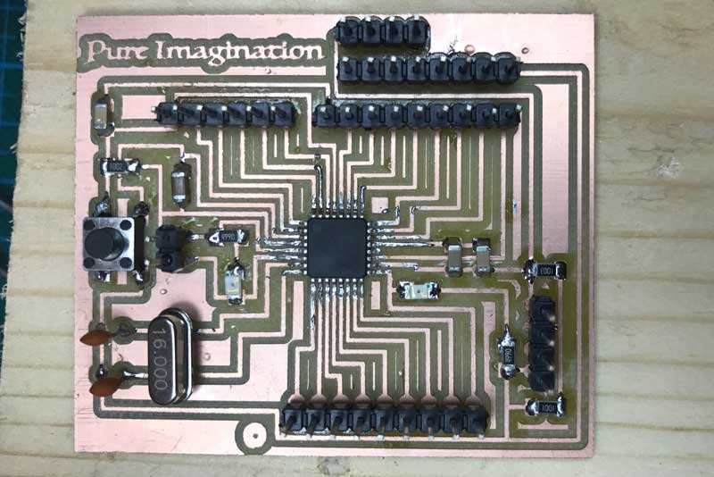
The next step is to upload the Arduino bootloader for an Arduino Uno to the controller. This can be done with a programmer or even another Arduino. I used a programmer as per the SatschaKit github. I was having all kinds of problems with it though. First, I found the pads around the 16mHz resonator are small and were not making good contact. I did a bad job. The, I needed to update the Arduino Uno board manager. Next, I found fabISPs in the lab, mine and others', were having a tough time consistently uploading sketches. Sometimes the uploading process would simply stall.
After much consternation, I was able to get the bootloader then blink example uploaded to the board via a fabISP. However, I still am unable to upload sketches directly through an FTDI. I get a message about programmer not responding and then it tries again for 10 times. And, the fabISP is miss far more than make now for uploading.
Takeaways : And that brings me to now, a couple hours before the final blog updates for the session. I tried to spiral up to a more robust data logging controller but fell a little short. I will continue to debug this board design and fabrication until it works. I hope having more data helps me to optimize this particular setup of microbial fuel cell, share with other researchers, and develop more efficient systems of electricity generation. And, I do not like the wood frame at all. I will change that in the next iteration after the electronics are improved.
I will post links to resources I have found helpful here.
Share this post...
« Previous post :: Grow module | Design and fabrication
My idea is to first create a small modular testing garden. I began with some sketches on paper and Rhinoceros. The bioelectrochemical modules are red and the frame is purple. I think this way will be able to be broken down and assembled easily and can be grown or reduced by adjusting the array. While the sketch shows a six by six array, I might reduce it to five by five. The testing modules were essentially cubes. This module is has a smaller bottom half to create a lip for sitting on the structure. In the upper portion there is...
Next post :: CNC milled wood frame »
I would like to use 2 dimensional milling to cut a wood frame to carry the concrete grow modules and hide the electronics. There will be a small cut-out on one side for an LCD which will be displaying data coming from sensors across the system. The concrete casting process was not precise due to some flexure in the walls of the mold. Each module has an extra 4-5mm total width in both directions. So the first part of making the frame was to compensate for this error. I should note, I kind of like the little bit of error...