Tags
#composites
#model3d
#cut3d
#pureImagination
#mold
Pure Imagination
- Environmental monitoring with online data logging to Thingsv
- Inventory
- Hessian/ burlap/ crocus composites
- CNC milled wood frame
- Grow monitors | What watches the watchers?
- Grow module | Design and fabrication
- Grow Module | The science
- Processing Light Graph
- Milling a composite mold
- Composites : Modular growth, testing
- Bio-electro-chemistry
- Bioelectrochemical testing pod
- LCD x Arduino
- Precedents
- Discussion
- Design, Materials and Methods
- History : Early concepts
2017 May 12
#composites
#model3d
#cut3d
#pureImagination
#mold
I am preparing a mold of four parts: two outside halves and two inside halves. Then I plan to make a burlap plus resin composite surface around the two inner halves. Finally, I use the outer halves to compress the composite as it cures. I have yet to try milling multiple surfaces from one block of material. Well, until today. The inner halves each require milling on two sides of the material.
I sized the molds to the constraints of our lab's Roland MDX-40A benchtop CNC machine. The XY maxes are 305mm according to the manual. Z max is dependant on the endmill. Unfortunately, doing so required me to scale my design further. The final molds will likely need to be produced on a larger milling bed.
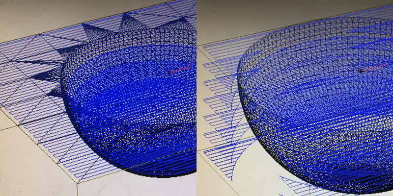
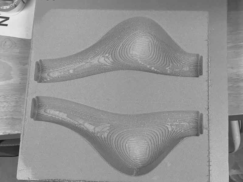
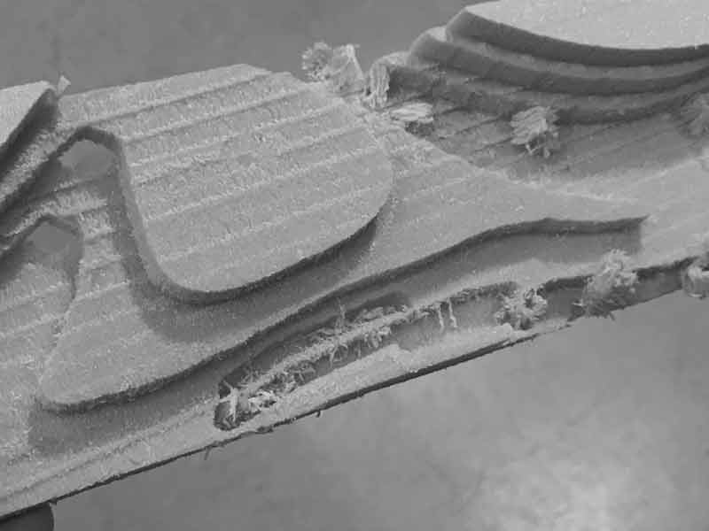
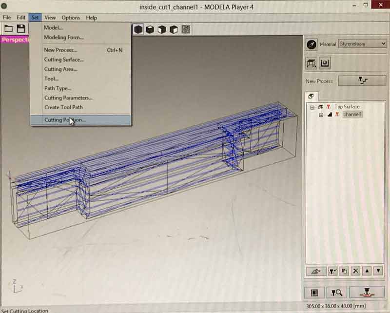
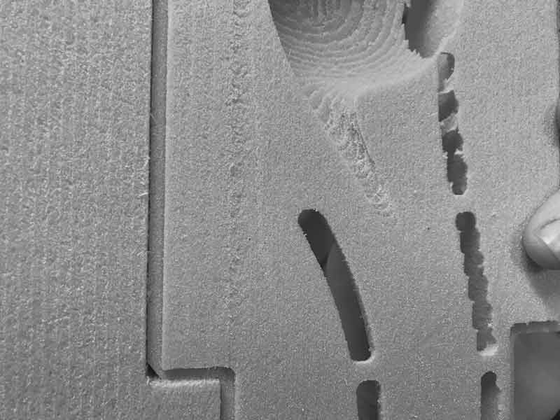
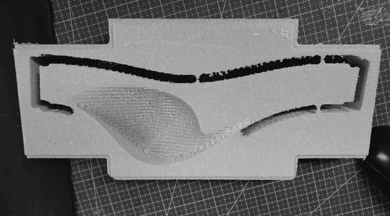
I noticed Modela Player likes rectalinear, parallel to X and Y, edges on models. If the model does not have rectalinear edges, the application assumes you would like some and proposes excessive tool paths. The left half is with a rectangular surface on top, the right without. The right has extra cutting to the maximum model Z-depth.
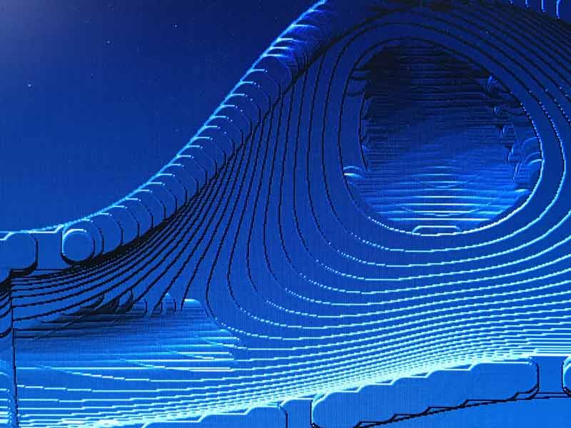
Speaking of tool paths, I intended to leave some degree of extra stock so the tool paths would be an expressive texture on the final composite surface. One important limitation to consider: Modela Player only has three options for tool path generation (unidirectional, contour, spiral) and may make some adaptations within these according to your model. For that reason, and because I think the application is limited in other respects for tool path generation, I will in the future seek other methods for my picky jobs.
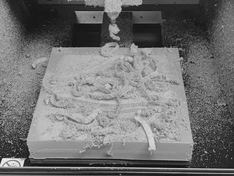
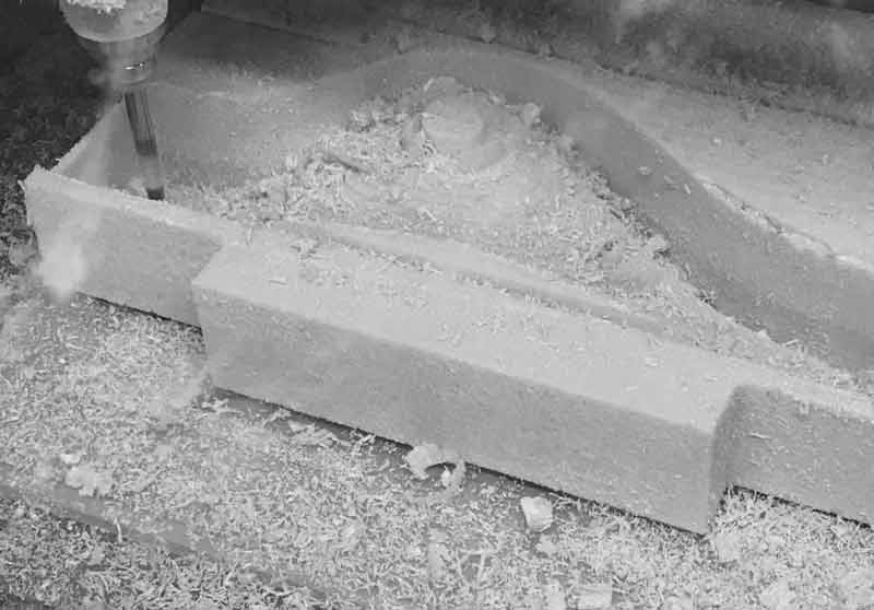
After starting the job I noticed the mill's travel speed was painfully slow. Why for such an easy to cut material? The preset material I used in Modela Player was poorly optimized. Then Neil Gershenfeld's voice echoed in my head, always do a small test. Okay, stop the machine and cut some pockets.
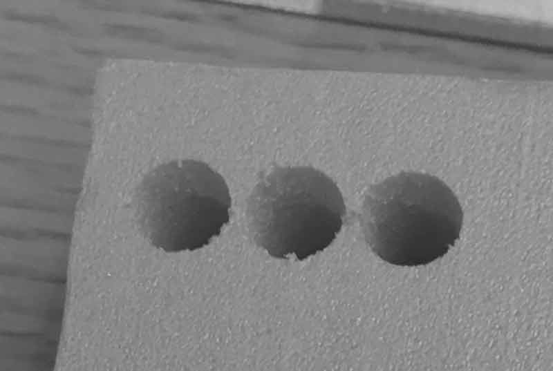
I maxed out the XYZ travel speed on the machine at 30mm/s. I was happy with it at the time. Next time though, I might look deeper into why the travel speed was locked to 30mm/s max. Be aware that rough cutting may produce an overabundance of excess material which can adversely effect the outcome. You can prevent this by reducing the XY step, for instance at 50% of the endmill diameter. However, that will add time to the job. Stop and clean periodically or mill longer and clean at the end. The decision is yours. +50% offset:
=50% offset:
The outside halves cut much faster with the speed updates. I will never cut both halves in the same tool path again. The bit kept moving from one half to the other on each layer and at probably a 50% tax on my time. Also, it is painful to see the mill move back and forth over the top surface of the material that I never intended to cut but for the rectangle rule in Modela Player.
I setup a system for cutting the inside halves with a 90 degree rotation of the stock after one surface was cut. This was a bad idea. The two surfaces could be cut on opposite sides of the mold much simpler. And, midway through the rough cut of the second surface, the mold dislodged slightly from the acrylic base and moved. Perhaps it could be salvaged but I resolved to do this flipping better.
The bottom side of the polystyrene was warped. Surface adhesion was thusly poor. Almost as poor as decision making.
The 90 degree rotating mill idea was broken in too many ways to count. It is not even worth the effort to document. While examining the aborted fabrication, it occurred to me I could simply mill on opposite sides. Back at the drawing board, I changed the inner halves to be flipped 180 degrees in between cuts and setup a system. The model uses the machine to make two cuts that will subsequently serve as a jig.
In the previous cutting I slightly miscompensated for the machine's chuck and it rubbed against the form's surface.
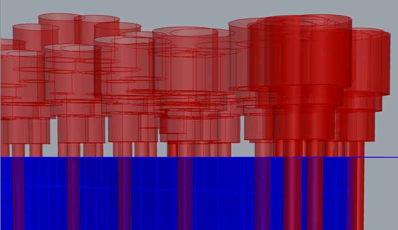
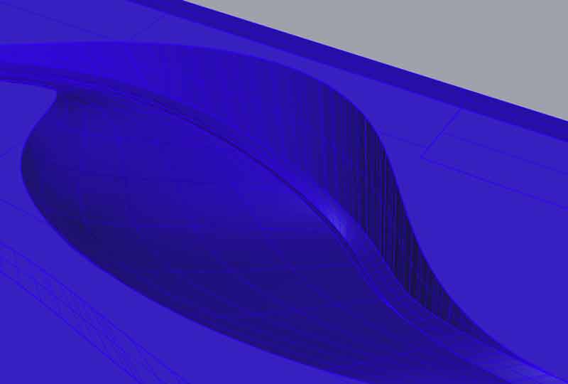
In response, I built a grasshopper model to help me precisely check for collisions by making a variable end mill, collet, chuck sizing and automatic surface population for visualization. This is very helpful. Someday, I would like to find or build a script that executes the mold setup process and accounts for these same variables.
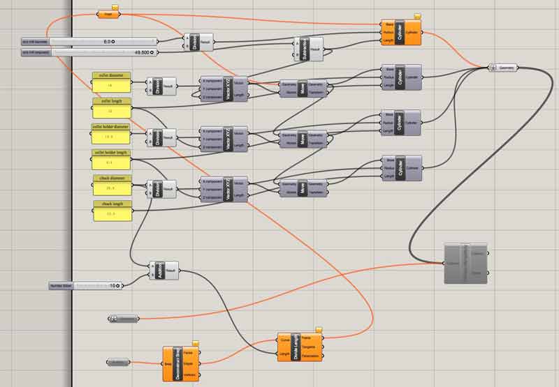
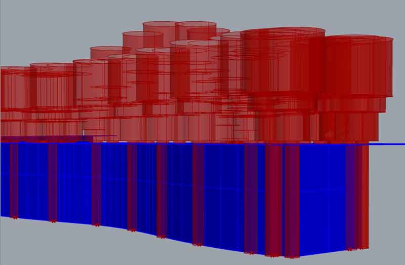
In this zone, the collet was going to be dangerously close to the upper surface near the end of a cutting job. The easiest solution in modeling was to lower the top surface so the mill first cuts the potentially conflicting material, then cuts deep.
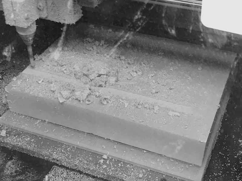
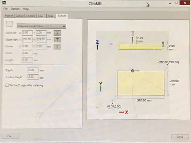
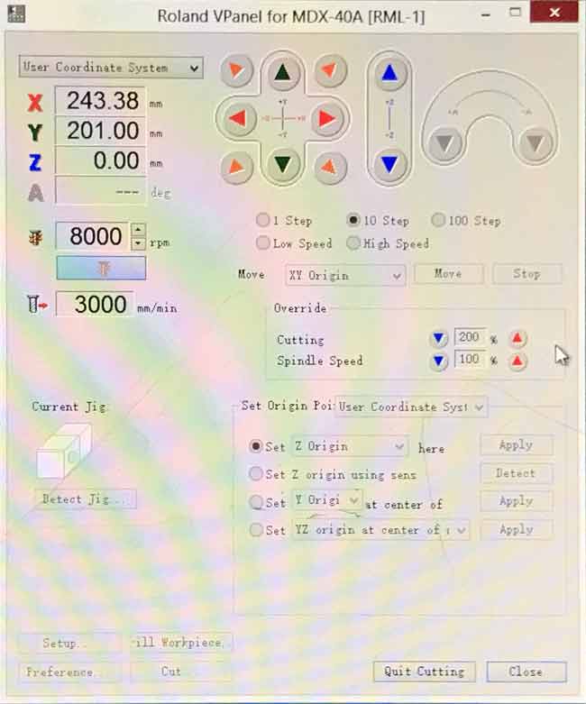
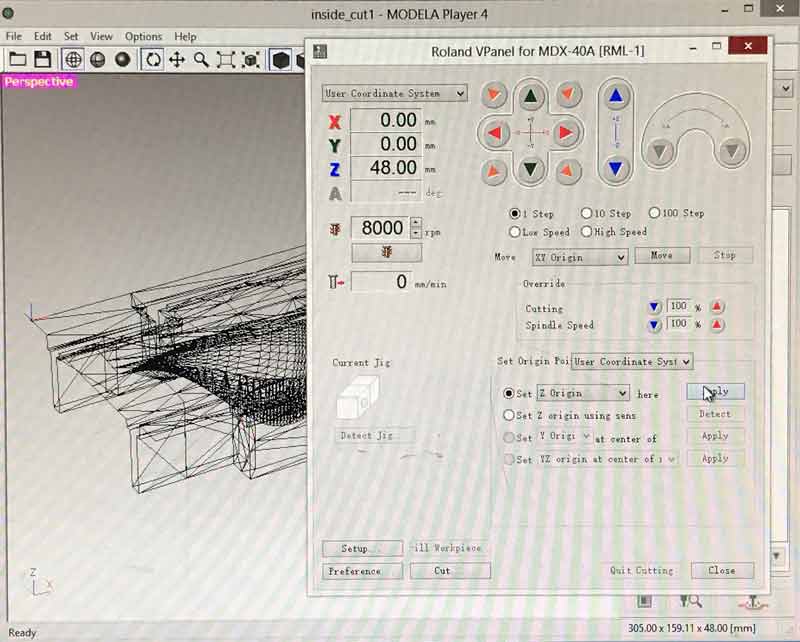
Back in the lab to see if my digital efforts produce better fabrication. I start by cleaning up the machine bed and milling one surface of a chunk of material level. An application packaged with the mill called ClickMILL makes this easy. I put my material into the mill, used the VPanel application to find the outer dimensions, inputed the numbers here and cut 2mm off the top of the stock. Instead of adjusting the Z precisely for the differentiation along the warped surface, I adjused the Z zeroing within the user coordinate system in VPanel. It is quicker.
When saving the file in ClickMILL, a dialogue will ask for more configurations. The max travel speed only went to 1800 which is too slow.
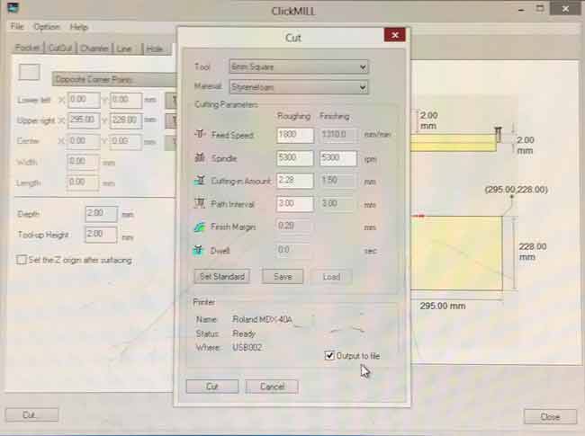
So you can maximize it in the VPanel while the job is cutting. This is a good way to adjust the speed on the fly.
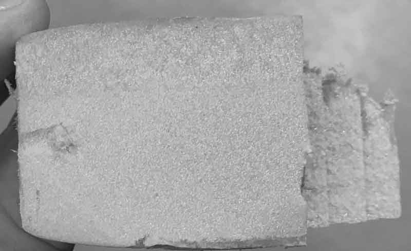
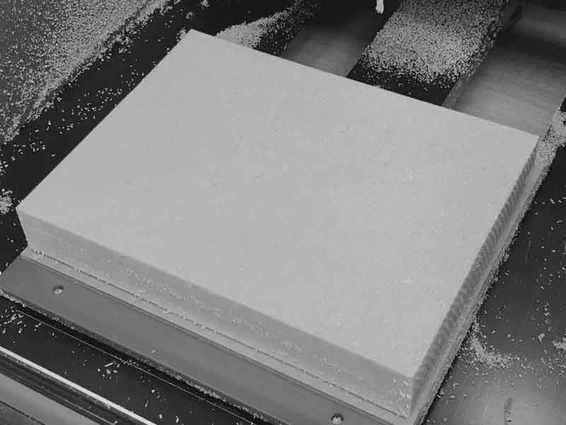
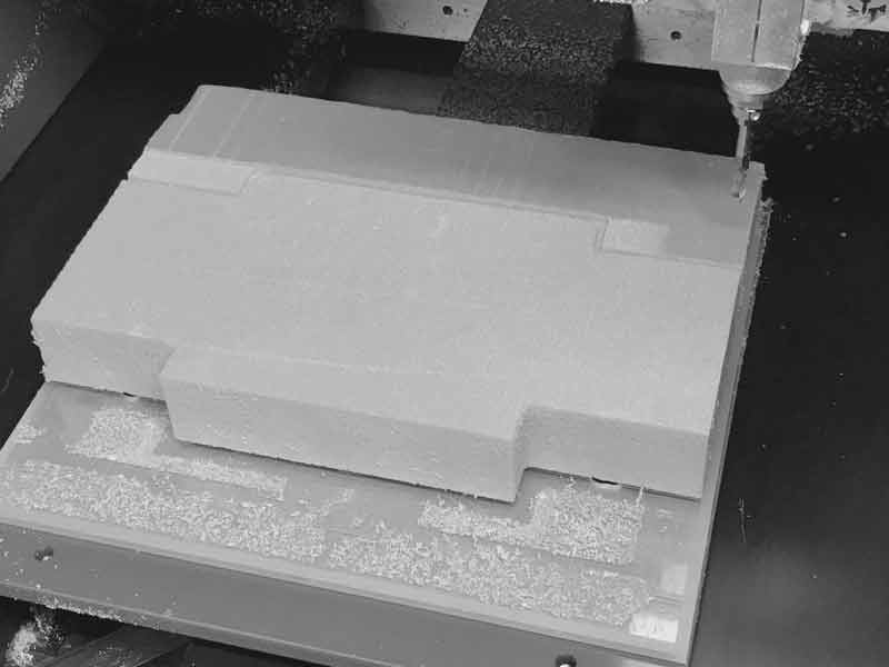
This photo may not look like much but the little bit of extra effort might have been the most effective steps today. A stable milling surface produces a happy mill. The opposite side will be surfaced while cutting the shape.
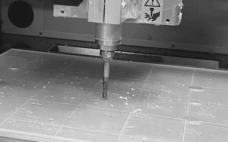
Before adhering the freshly milled surface, I carefully calibrated the endmill as near as possible to the sacrificial layer without any collision. The thickness of the shape nearly matches the material thickness which prevents me from keeping the endmill far from the sacrificial layer. Further, our lab does not have a great way to make a thin polystyrene sacrificial layer. That aside, this machine is built for precision and accuracy and it delivers.
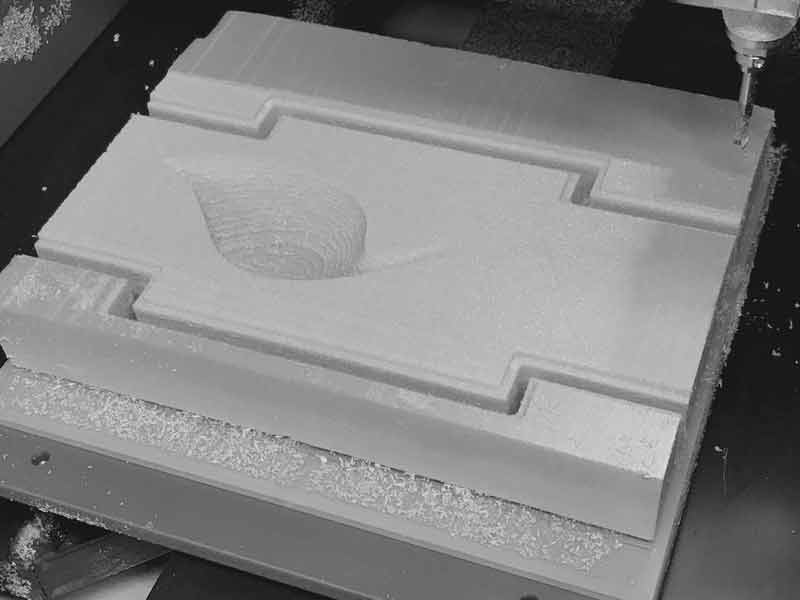
To optimize milling time and keep the material stable throughout the job, I setup four jobs for this side. Rough and finish cuts for the shape. Then the green channel followed by the cyan channel. There are a few ways this could be accomplished, I chose to export each zone as an individual STL.
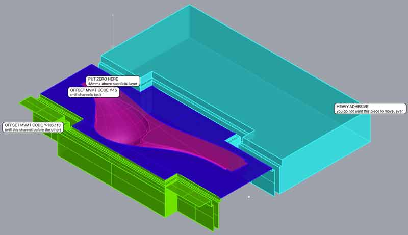
First set the Z to match the model height precisely: 48mm. This is regardless of the precise top of stock. It is easier to mill a little air than adjust a three-d model and movement code for what is infinitely variable surface thickness from one piece to the next in polystyrene and you need to know the material thickness precisely when the material is flipped. Imagine aligning two floating surfaces relative to one another within a box of unknown dimensions and you can only orientate the surfaces to the surfaces of the box. Another method would be to take measurements of the stock and update a parametrically driven 3D model. Alas, the mold portion of this model was not parametric. Furthermore, new movement code would have to be created for every new cut, this way the same movement code can be used every time.
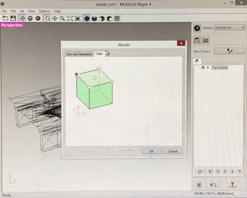
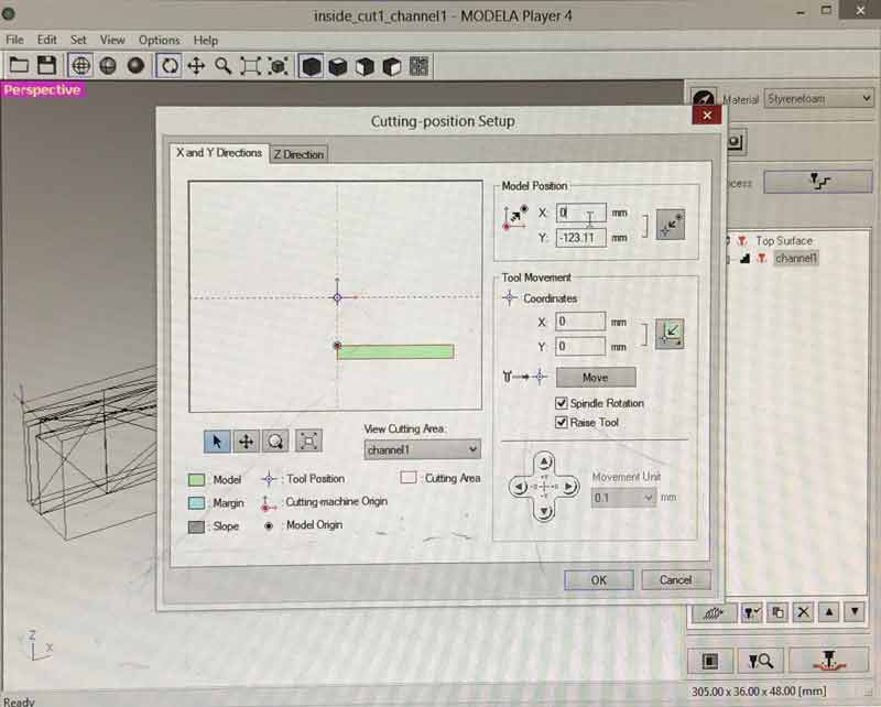
Decide on one XY origin and stick to it for all the jobs. Mine is the upper left corner. It aligns with the flip.
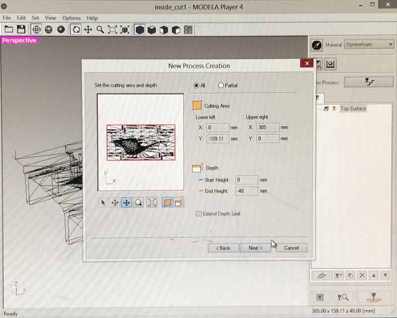
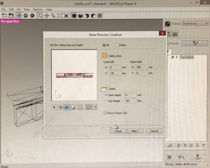
Keep an eye on the depth. -48mm, perfect.
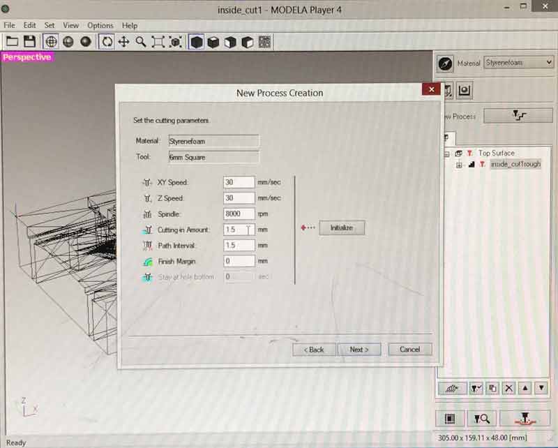
Optimize these settings for polystyrene. I set my finish with 1.5mm offsets, tool paths are fine with me for this prototype.
I am using the same XY origin for all the files. Adjust model position accordingly. Spoiler alert! I forgot to do this for the shape file, the first thing I cut, and did not realize it until the end. Should have been a 16mm offset.
Always check the model depth is as anticipated.
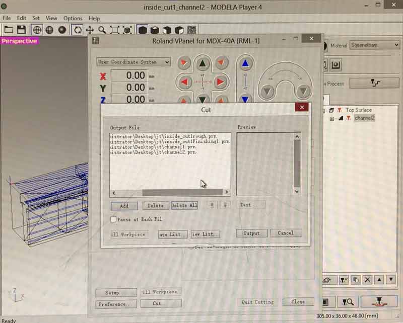
Every job uses the same endmill. Queue. Release the hound.
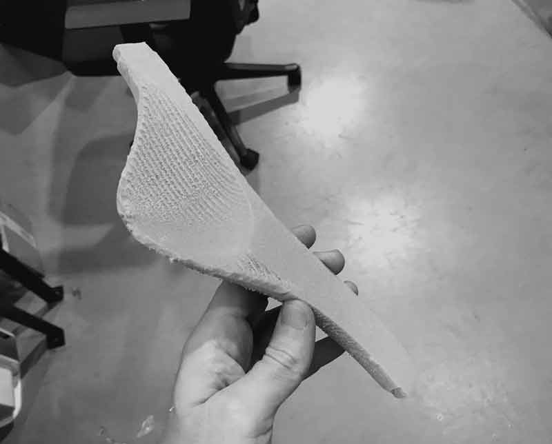
First side cut beautifully.
Flipped and locked in place.
After cutting nearly to the bottom of the stock (and gently colliding the collet with the top surface as predicted by my grasshopper clearance check), the mill returned to the top to remove material before returning for the final 5mm along the bottom. I have not discovered why the movement code (one job) was organized in this manner. ̑
And after all the effort, the model was offset by 12mm. I will offset the movement code for the first cut, reduce the frequency and size of the dogbones and recut tomorrow.
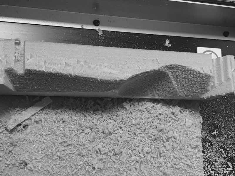
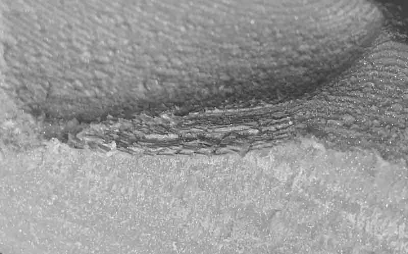
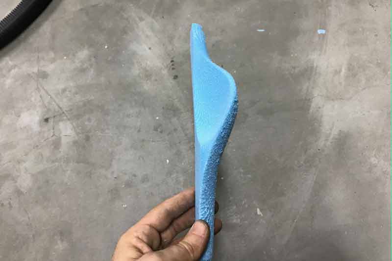
Update: I returned to the mill and adjusted for the missed offset of the first surface I milled. Instead of using a contour path on the finish cut, I used scan lines along the long axis which sped up the job considerably. This time, it was mostly successful. I did not give the form enough error protection in the 3D model and the piece remained ever so slightly locked in the mold.

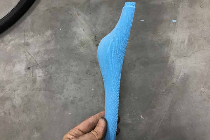
I freed it with a foam cutter. This half is ready.
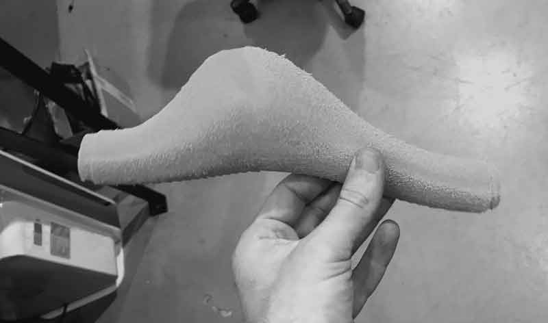
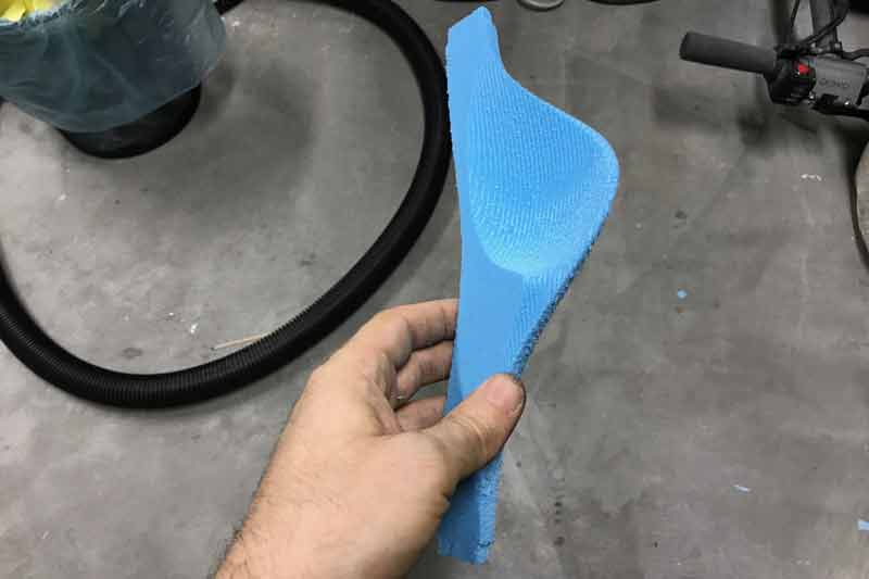
Then I added an offset channel along the edge of the surface on the top side and forced the opposite side to cut deeper. Next time the model will not be clinging to the excess foam.
After mirroring the digital models and making some positioning adjustments for flipping I cut the other half of the inside piece. After flipping, I taped some extra pieces of foam to the board to help hold the piece I was cutting in place because there is so little space to do so on that piece. This time, the piece was cut beautifully.
Download project files
I will post links to resources I have found helpful here.
Share this post...
« Previous post :: Composites : Modular growth, testing
Composite materials are made of two or more constituent materials, each with significantly different, yet complimentary, physical and or chemical characteristics. When combined into a composite, the team of materials is greater than the sum of its components. I started the project by mocking up a form in Autodesk Maya. The form is like bamboo in that it grows in sections and has openings to contain the moss. At this point, rather than spending much time modeling this object, I would like to jump into making composites becasue it is my first time. This is a little mockup of what...
Next post :: Networking light : Twin PCB »
I was introduced to a project by Enrico Bassi which uses two ATMega boards connected to IR Sensors and IR LEDs to network by reading pauses in IR light (low). Upon seeing it, I was immediately impressed with the visceral qualities of networking with light. It is visible to our eyes! And, we could control a light in our hands to communicate to a machine. Admittedly, low tech stuff here. Remote controls... Plus, technically, we cannot see the light, the red LED on Bassi's board is for human reference, the IR LED is invisible to us. Regardless, as a first...