Tags
Electronics production
- Eagle : Export PCBs quickly with this script
- Grow monitors | What watches the watchers?
- Networking light : Twin PCB
- Phototransistor breakout board
- EAGLE pt2 : Fabricating the circuit board
- Fabricating, wiring, learning
- LCD ATTiny44 PCB
- EAGLE pt1 : Designing a circuit board
- Stuffing a circuit board
- Milling a circuit board
2017 May 16
#electronics
#cut2d
#elecFab
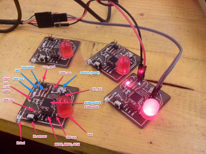
I was introduced to a project by Enrico Bassi which uses two ATMega boards connected to IR Sensors and IR LEDs to network by reading pauses in IR light (low). Upon seeing it, I was immediately impressed with the visceral qualities of networking with light. It is visible to our eyes! And, we could control a light in our hands to communicate to a machine. Admittedly, low tech stuff here. Remote controls... Plus, technically, we cannot see the light, the red LED on Bassi's board is for human reference, the IR LED is invisible to us. Regardless, as a first project to get into networking, I am game.
I start by breaking down Bassi's work. This is an image from his Fab Academy page. I added the component labels. I would like to do the design part of this build quick. Get into the fabrication and coding and then circle knowledge back out. In my head, I plan to pull the components from the first boards I do and re-use them in more advanced boards, working my way up to fabricating my own special Fabkit. That in mind, I start making some mods to his board. The blue labels I plan to eliminate.
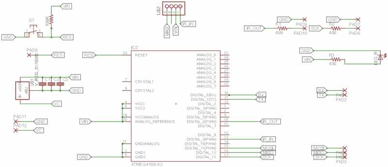
Upon investigating his code and build further, I believe this same thing could be accomplished with an ATTiny44. Indeed, in his post, Bassi mentions that he switched to the ATMega 328 early in his process because his testing code was inflated and later realized the 48 had enough memory for the final arduino sketch. Bassi's Eagle schematic:
I prepared a schematic of the IR Networking board using an ATTiny44.
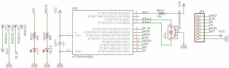
I had an idea that I would pull all the off board connections to one header but I am not sure it is going to work. Either way, I do not think it is worth the time. I will return to the lab, double check the inventory for an IR sensor, customize the pads and split the header.
I redesigned the schematic with through holes for larger LEDs and the IR receiver I found in the Shanghai electronics market. Then I added an ISP header and another 2x2 for external power and RX/TX.
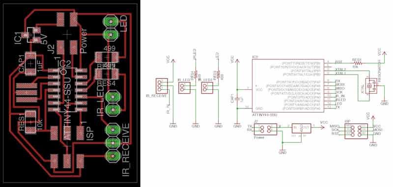
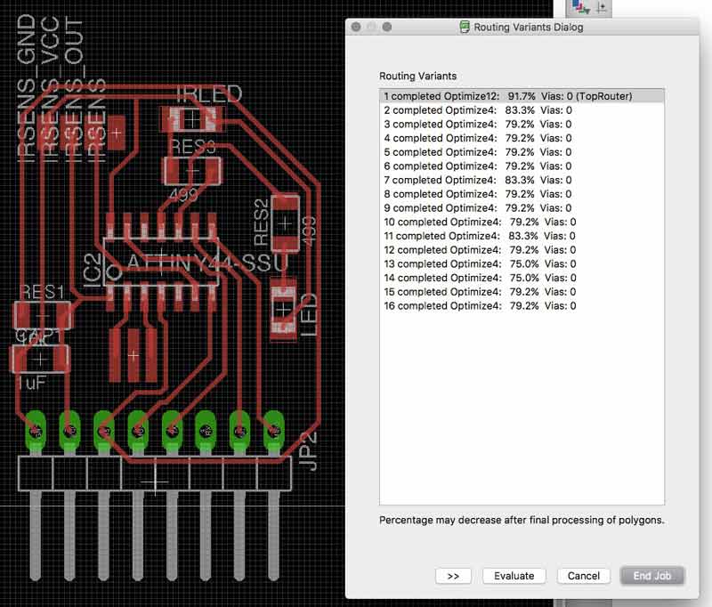
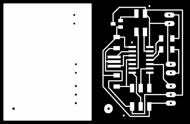
Outline and traces look like this in the computer.
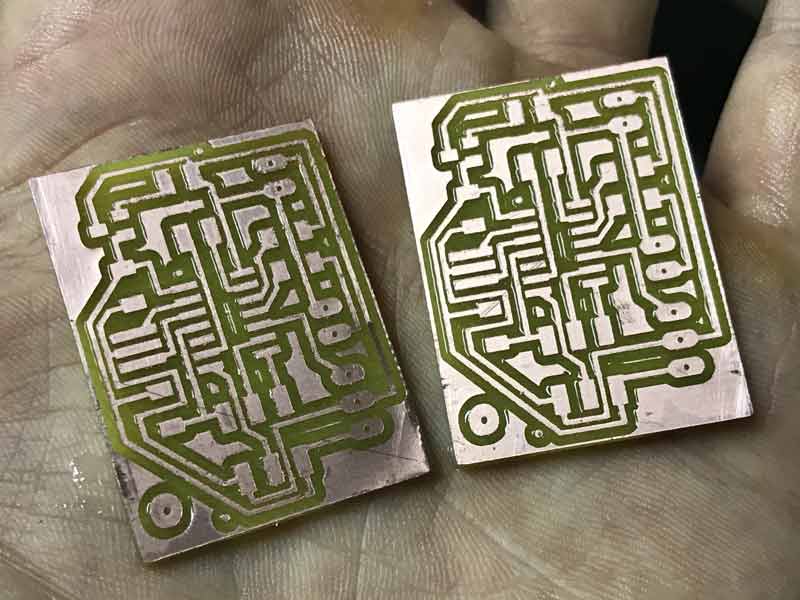
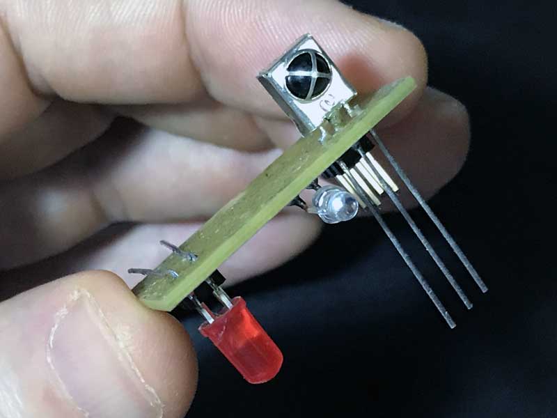
Like this in my hand a few minutes later.
And like this soldered a little while later still.
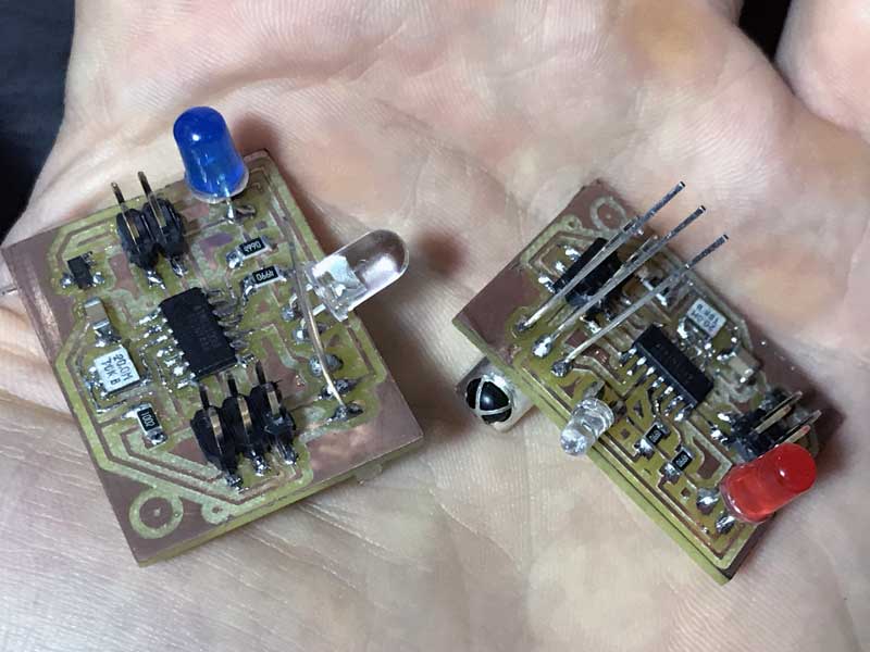
I made a mistake when orientating the three pins for the IR sensor. I should have mirrored the pins. And to do that, I might have to rearrange the lights and sensor to accomplish the traces without any zero ohm resistors. For now, I need to keep moving forward.
Download project files
I will post links to resources I have found helpful here.
Share this post...
« Previous post :: Milling a composite mold
I am preparing a mold of four parts: two outside halves and two inside halves. Then I plan to make a burlap plus resin composite surface around the two inner halves. Finally, I use the outer halves to compress the composite as it cures. I have yet to try milling multiple surfaces from one block of material. Well, until today. The inner halves each require milling on two sides of the material. I sized the molds to the constraints of our lab's Roland MDX-40A benchtop CNC machine. The XY maxes are 305mm according to the manual. Z max is dependant...
Next post :: Chinese calligraphy G-code encoder »
When writing Chinese characters, there are rules. You can either abide or you will be revealed a fraud. When we first tested the machine, we tried several online g-code generators (link?). One thing we did not find was a good way to specify stroke ordering and directionality. I was excited to show some Chinese people the first successful tests of our machine and everyone criticized the machine's stroke order! I started to investigate the possibility to write code we could use to generate g-code which follows the basic principals for patterning strokes in Chinese characters. And, this was a good...