Tags
Electronics production
- Eagle : Export PCBs quickly with this script
- Grow monitors | What watches the watchers?
- Networking light : Twin PCB
- Phototransistor breakout board
- EAGLE pt2 : Fabricating the circuit board
- Fabricating, wiring, learning
- LCD ATTiny44 PCB
- EAGLE pt1 : Designing a circuit board
- Stuffing a circuit board
- Milling a circuit board
2017 Apr 06
#electronics
#cut2d
#elecFab
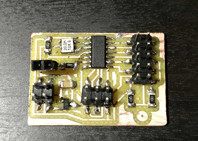
This dance is as follows: mill, solder, wire.
Familiar aesthetic for the board. Milling the traces at 0.10mm depth once again was unsuccessful so I dropped the depth to 0.15mm and milled on top of the previously milled stock. Soldering was significantly faster. This time, when heating the connections I kept a count in my head which varied from an one to three count according to the size of the components. Worked well in terms of pace. Checked all the connections with a multimeter. No problems. Initially I connected an incorrect resistor in front of the LED which took me a few minutes of failure to program communications with the LED to find. When I did, I pulled that fraud off the board and invited the right size in.
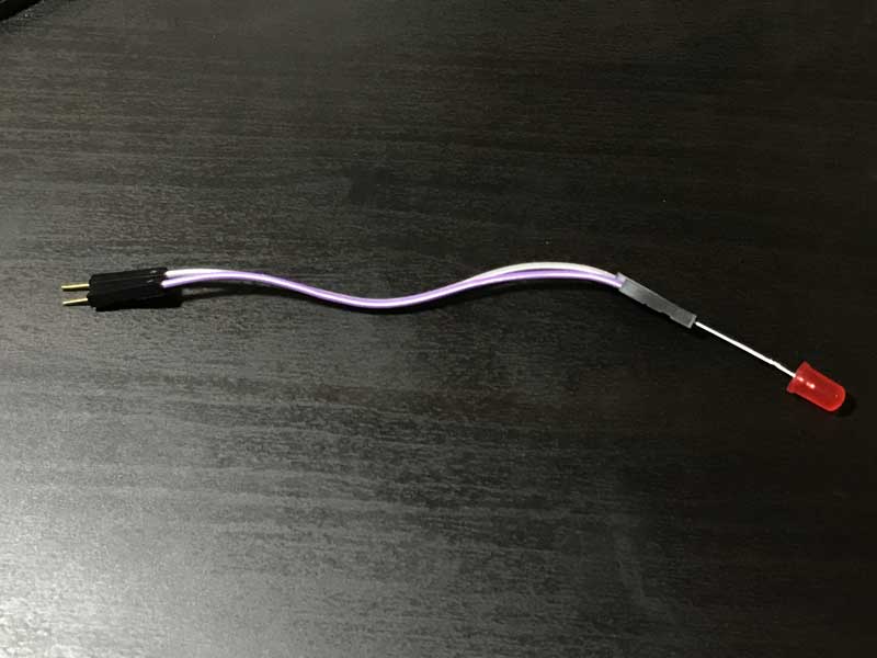
I soldered a 1*something female pin header to the LED. Easy connections.
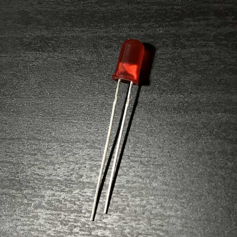
The shorter pin of the LED is the cathode side. Other signifiers: on the cathode side there often is a flat section of the rounded plastic base and the larger metal side inside.
LED extension cables.
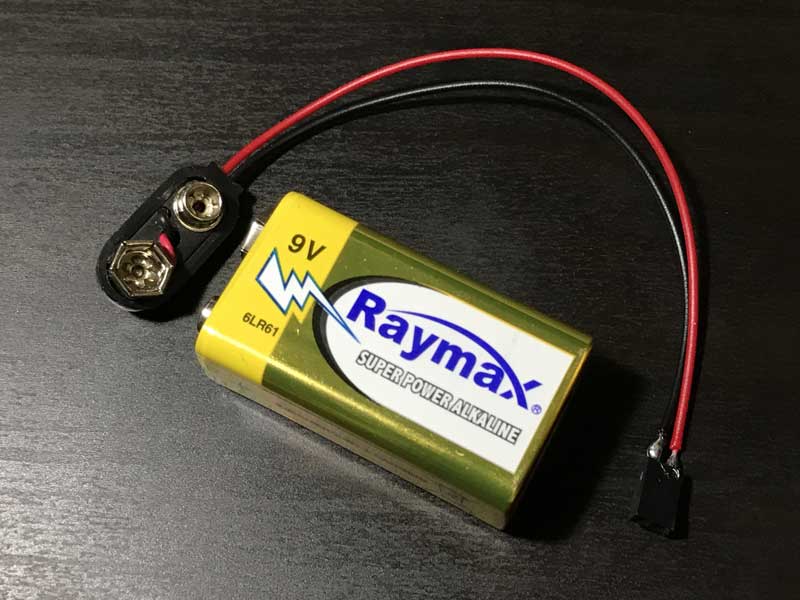
I am powering with this 9volt battery. This is a connection I soldered to a female pin header.
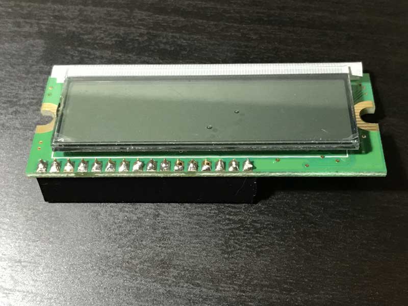
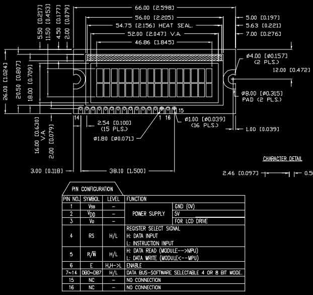
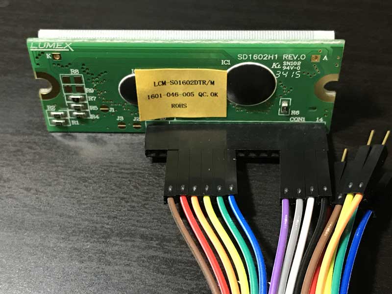
The wire connections to the LCD panel according to the datasheet.
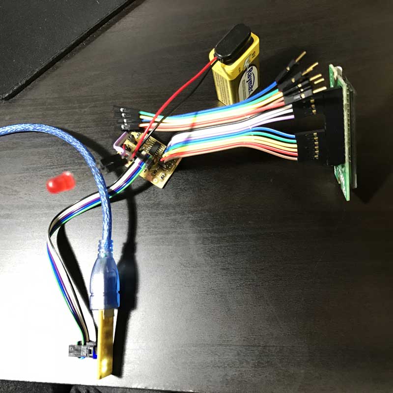
And finally. with everything connected, it is time to program.
Download project files
I will post links to resources I have found helpful here.
Share this post...
« Previous post :: LCD x Arduino
Arduino has a built in libary, "LiquidCrystal.h", for programming this type of LCD. I thought it would be fun to imagine a prototype of HAL 9000 prior to artificial intelligence using the LCD display to communicate and the LED to hint life. Arduino IDE is packaged with many sketches of LCD functions. Browse to File > Examples > LiquidCrystal and you can check those out. First, write in the sketch the command to send the library for the LCD. #include <LiquidCrystal.h> Then, you need to dictate which MCU pins are connected to the RS, E, DB4-7 pins of the LCD...
Next post :: EAGLE pt2 : Fabricating the circuit board »
I need to export the board design from EAGLE, generate the mill paths and solder the electronic components. The board is ready to be cut; EAGLE's job is complete. Time to export. From the View> Layer settings... menu, set all the layers to invisible except Top, Pads and Dimension. Export the file as a monochrome PNG at 1500 dpi. The PNG may not be exported in perfect condition but can quickly be edited in a PNG suitable editor, i.e. Photoshop, Inkscape. I did not find a good way to export a PNG for the outline cuts. EAGLE has a thin...