Tags
#electronics
#elecFab
#tutorials
Electronics production
- Eagle : Export PCBs quickly with this script
- Grow monitors | What watches the watchers?
- Networking light : Twin PCB
- Phototransistor breakout board
- EAGLE pt2 : Fabricating the circuit board
- Fabricating, wiring, learning
- LCD ATTiny44 PCB
- EAGLE pt1 : Designing a circuit board
- Stuffing a circuit board
- Milling a circuit board
2017 Feb 25
#electronics
#elecFab
#tutorials
Freshly produced PCB in hand, it is now time to solder the electronic components. Soldering is tricky. Repetition is key. I am beginning to find an effective method varying my practice, trial and error. This is a road map of component placement from the FabTinyISP page.
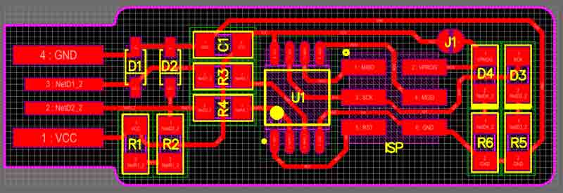
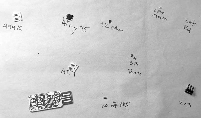
First, gather the components, or do not. I soldered two boards. The first, I gathered everything beforehand, the second time I grab componenets from their storage as I went along. Whatever, both worked. Just be careful not to lose any or return to the wrongly marked storage. The microcontroller and diode components are directional; all others are nonspecific.
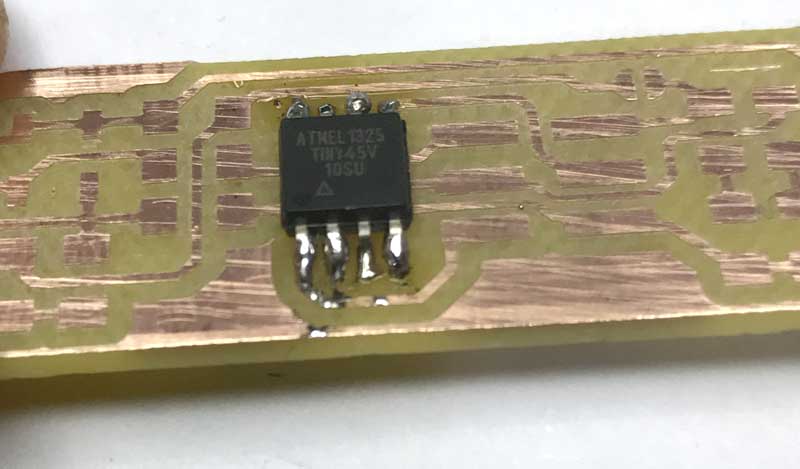
- U1 : 1x ATtiny45 or ATtiny85 (directional)
- R1, R6 : 2x 1kΩ resistors
- R2, R5 : 2x 499Ω resistors
- R3, R4 : 2x 49Ω resistors
- D1, D2 : 2x 3.3v zener diodes (directional)
- D4 : 1x red LED (directional)
- D3 : 1x green LED (directional)
- C1 : 1x 100nF capacitor
- IDC : 1x 2x3 pin header
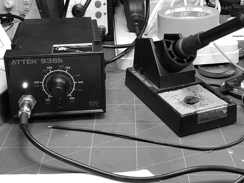
Preheat your soldering iron to around 400 Cal and make sure the tip is clean. When soldering heat the the tip of the connection, not the solder, then apply the solder. Start by flowing a small glob of solder onto one of the pads connected to a compoonent. Gently press the soldering iron onto the pad and after a couple seconds, apply some solder to the iron. If the copper is adequately heated, the solder will magically move from the iron onto the copper. If the solder bubbles, the copper is not hot enough.
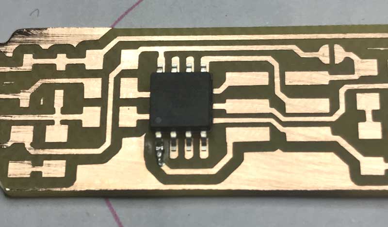
Grab the electronic component, this time the ATtiny45, microcontroller, with some tweasers, reheat the applied solder glob with the hot iron and slide the microncontroller into position in the solder. The microcontroller is directional, align the small dot on the microcontroller to the roadmap. With this action, the component is tacked in position.
Next, press the soldering iron tip onto the pad and electronic component connection, simultaneously heating both. After a couple seconds, add solder. The solder will flow into and around well-heated connections. After adequate solder is flowed, remove the solder, then the iron. Good joins have a flat electronic component and shiny solder completely wrapping the connection. Bad connections can be reheated and fixed. Components can also be removed by reheating the connections and pulling the components from the board. When all the connections are soldered, remember to flow the first tack spot.
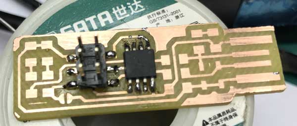
I started with the microcontroller because it is the most difficult to solder. Next I did the ISP which is also difficult.
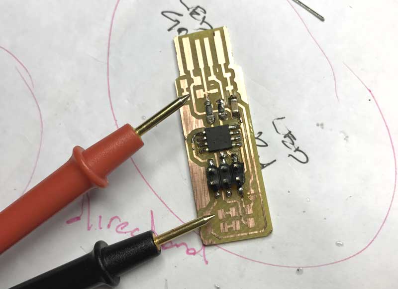
As I soldered components, I checked their connections with a multimeter. I put the multimeter to the check mode with sound. Follow the traces to check connectivity by pressing one wand to the connection point and the other further along the trace. Sound means connection. If that connection is undesired, check for extra solder. If no connection, re-flow solder at the intended connection.
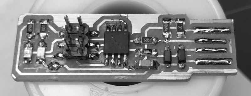
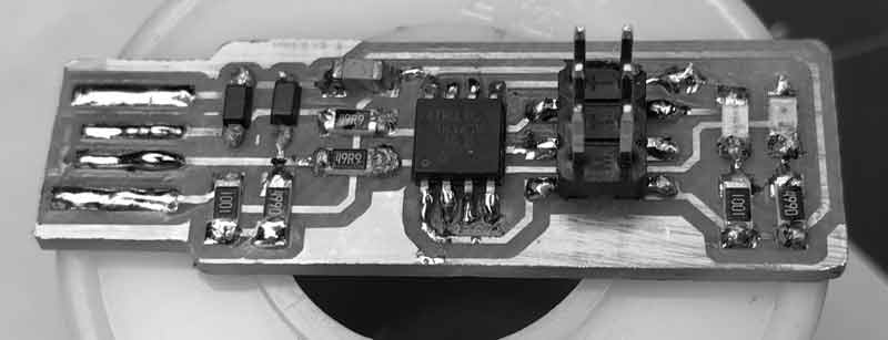
After about an hour of soldering and testing, I have what I hope will be an operational programmer. My second go around. I added solder along the USB leads to improve connectivity.
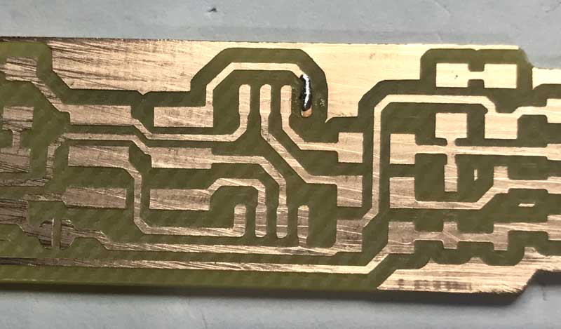
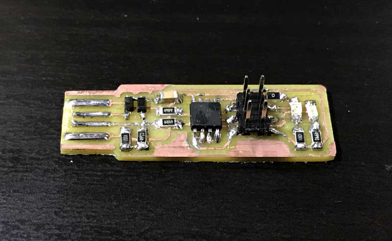
This is a photo of my first attempt, which I have yet to get operational. I do not hold out hope for this one...
I will post links to resources I have found helpful here.
Share this post...
« Previous post :: Programming a programmer
An in-circuit serial programmer (ICSP) is capable of programming microcontrollers on various boards with only a universal serial bus (USB) cable and 6-pin insulation-displacement contact (IDC) to 6-pin IDC cable. The ICSP vastly simplifies what would otherwise be an expensive and laborious process across different chip types. First I installed Crosspack on my mac. Crosspack is a development environment for AVR microcontrollers and necessary to give the terminal app capability for the upcoming task. Next, from the FabTinyStar page, I downloaded the firmware source code. I added a link here as well. You can open the Makefile with a neutral...
Next post :: EAGLE pt1 : Designing a circuit board »
EAGLE is a scriptable printed circuit board (PCB) computer aided design (CAD) program for 1. creating relationships between electronic components, for which you may download and curate libraries, then 2. positioning the components on a PCB and drawing traces. EAGLE stands for Easily Applicable Graphical Layout Editor. As of 2016, EAGLE was acquired by Autodesk Inc. The EAGLE is split into two primary GUIs: Schematic and Board graphs. You will use the schematic graph to select and interrelate the electronic components to be soldered on the PCB. The board graph is used to arrange the components and draw traces, pads,...