Tags
#electronics
#coding
#microCode
Embedded programming
- Environmental monitoring with online data logging to Thingsv
- Grow monitors | What watches the watchers?
- LCD x Arduino
- Programming "Hello to the World" with C
- Breathing light : An arduino experiment
- Datasheet Atmel ATtiny24/44/84
- Echo : Programming.c
- Programming a programmer
- Arduino IDE, introduction
2017 Feb 25
#electronics
#coding
#microCode
An in-circuit serial programmer (ICSP) is capable of programming microcontrollers on various boards with only a universal serial bus (USB) cable and 6-pin insulation-displacement contact (IDC) to 6-pin IDC cable. The ICSP vastly simplifies what would otherwise be an expensive and laborious process across different chip types.
First I installed Crosspack on my mac. Crosspack is a development environment for AVR microcontrollers and necessary to give the terminal app capability for the upcoming task. Next, from the FabTinyStar page, I downloaded the firmware source code. I added a link here as well. You can open the Makefile with a neutral text editor, such as TextEdit or Brackets, applications common to this blog. It is important not to change Makefile's formatting or extension. Makefile displays setup information, commands, and some variables such as the MCU, PROGRAMMER, F_CPU (Clock cycles), which need to be set specific to your programmer. I am using a previously built FabISP to program my new programmer.
♻ FabTinyISP firmware source code ♻
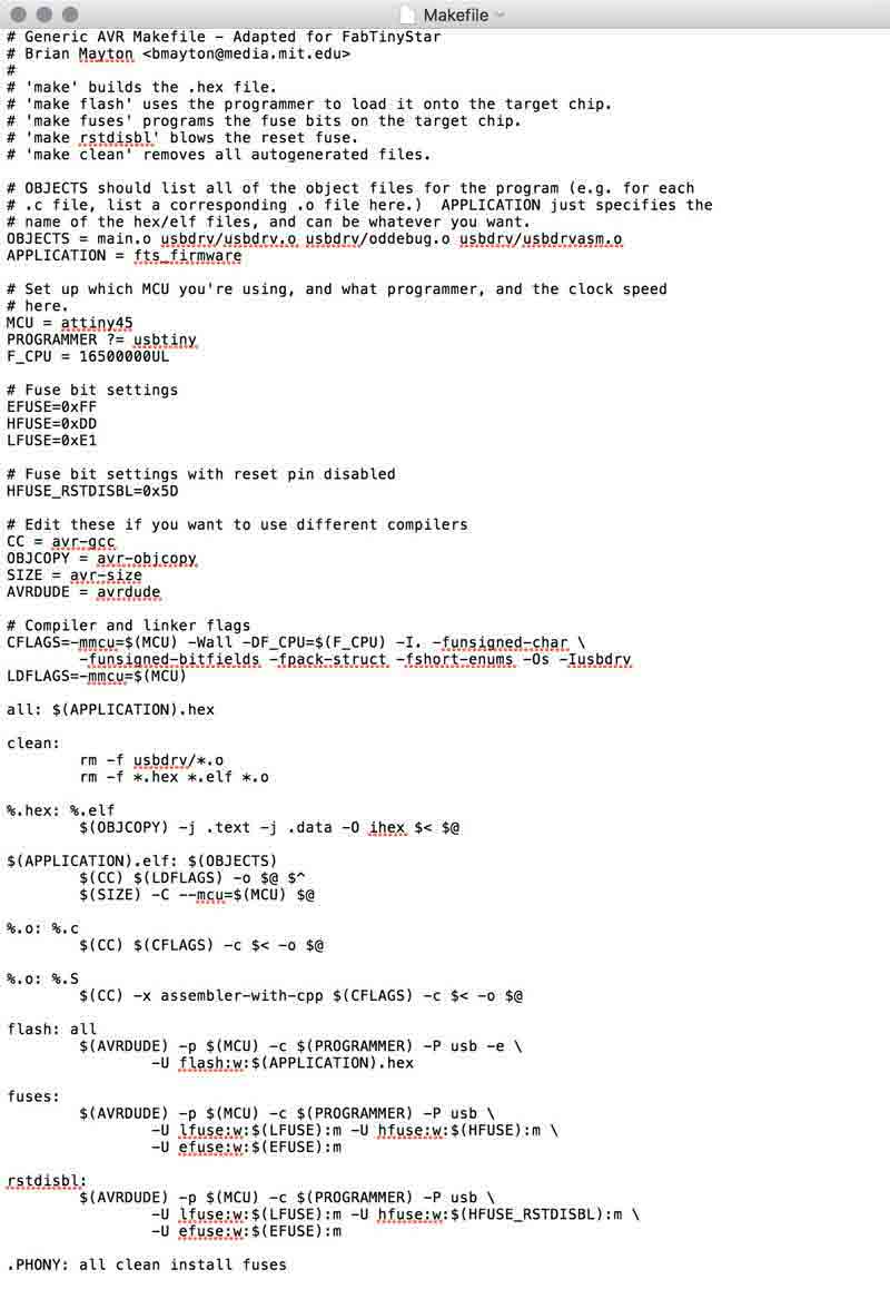
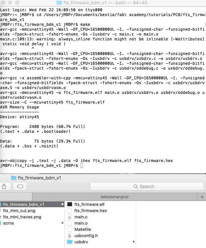
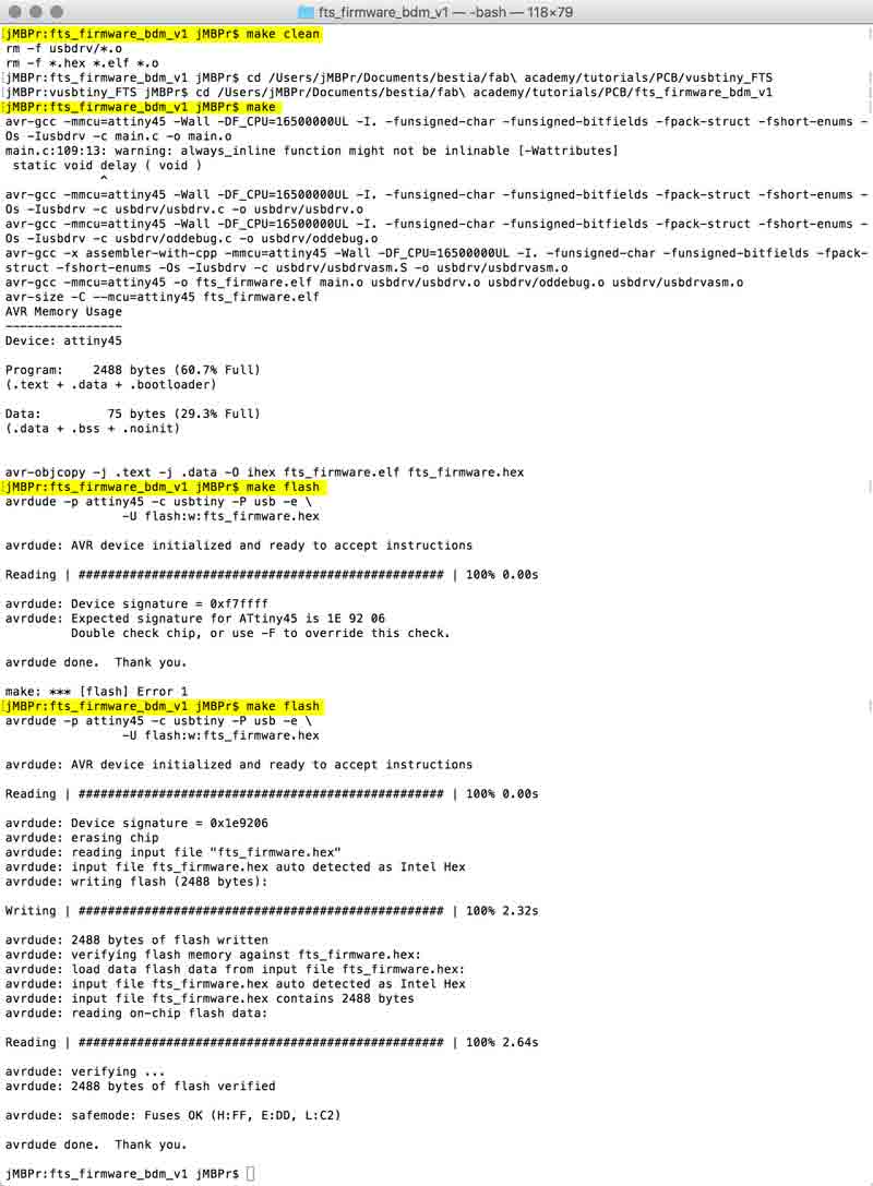
In terminal, cd (firmware location), then give the command "make". This will create some new files listed on the second to last line including fts_firmware.hex.
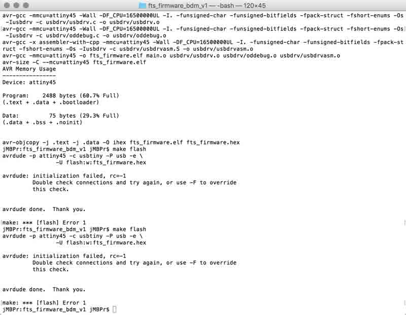
Now with the programmer connected to the newly made ICSP give the command "make flash".... and, fail. "make: *** [flash] Error 1". I could not work around this error in the terminal environment.
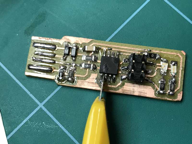
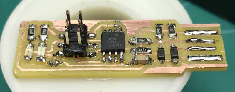
After the receiving Error 1, we checked the connections with a multimeter. Follow the traces to the connections and check that adjacent connections are not giving feedback. In this case, The first and second connection of the ATtiny45 were mistakingly bridged.
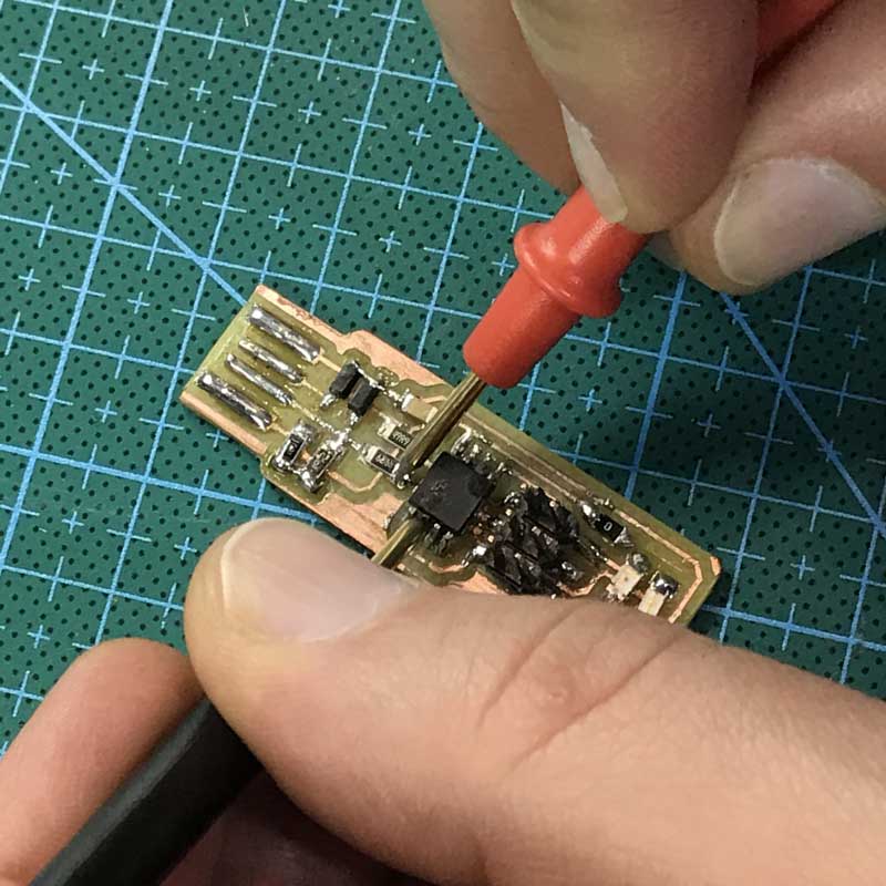
I severed the connection with a blade. Having these two spots connected would definitely cause problems. I will return to my mac with new hope.
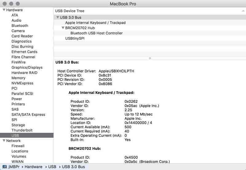
Unfortunately, I still am receiving the same error from my terminal. Unable to solve the problem, I have opted to start again from scratch. The following screenshot of my About this Mac > System Report shows a successfully connected FabISP. Not mine. Yet.
Update: I have a new board. This one is prettier. This one is pre-tested. I think this one will become a working programmer. First I cleaned out the firmware directory.
make clean
Then rebuild the computer language files...
make
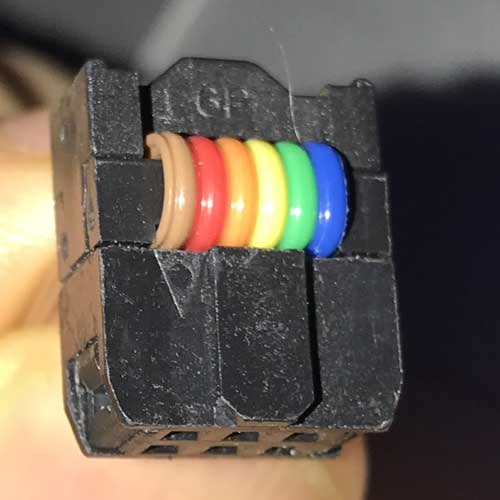
And send the instruction to the microcontroller. This will require a programmer connected to the 6 pin IDC with a programmer cable. Check the orientation of the programmer cable by aligning the marked connection spot iwth the dotted pin on the roadmap.
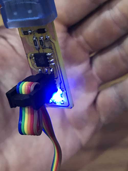
After the programmer is connected to your newly fabbed board, connect each to USB ports on your computer. At the very least, connect the programmer to your computer, the target board just needs some power. It can be connected to any USB port. When it is connected, the red diode should illuminate. If your fablab is like mine, blue diodes may have found their way into the red diode storage. In which case, someone was not careful with restocking!
When everything is linked, this command will tell the programmer to erase the microcontroller and program its flash memory with the contents of the hex file.
make flash
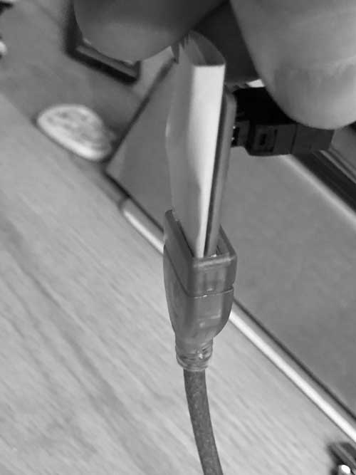
Error 1. This time however, the initialization succeeeded. "Expected signature for Attiny45 is IE 92 06". I searched Google for this specific error and found some tips written beyond my current scope of comprehension. Former FabAcademy student Yue Siew Chin had the same error and was able to resolve it: "The solution was very odd because it was after I heated up the chip area on the board a little with a hot gun or a hairdryer, it was able to load the program!" Okay, first I tried a low-tech fix: double-check the USB connection by adding a little paper underneath. Success!
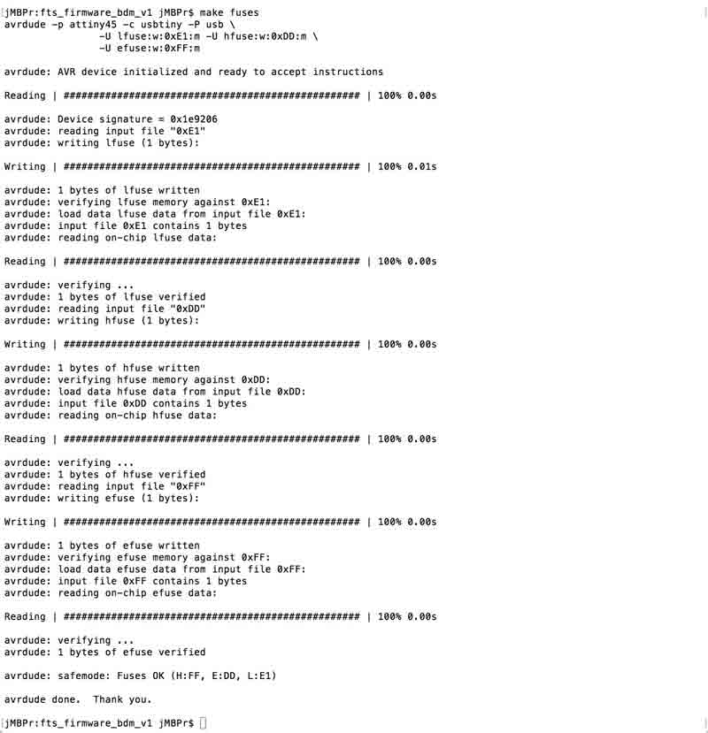
Now make fuses, which will setup all the fuses except the one that disables the reset pin.
make fuses
Check the USB functionality by plugging the board into your computer and checking the device page for the new programmer. Here it is: USBtinySPI.
One last step: blow the reset fuse. First reset the the disable pin.
make rstdisbl
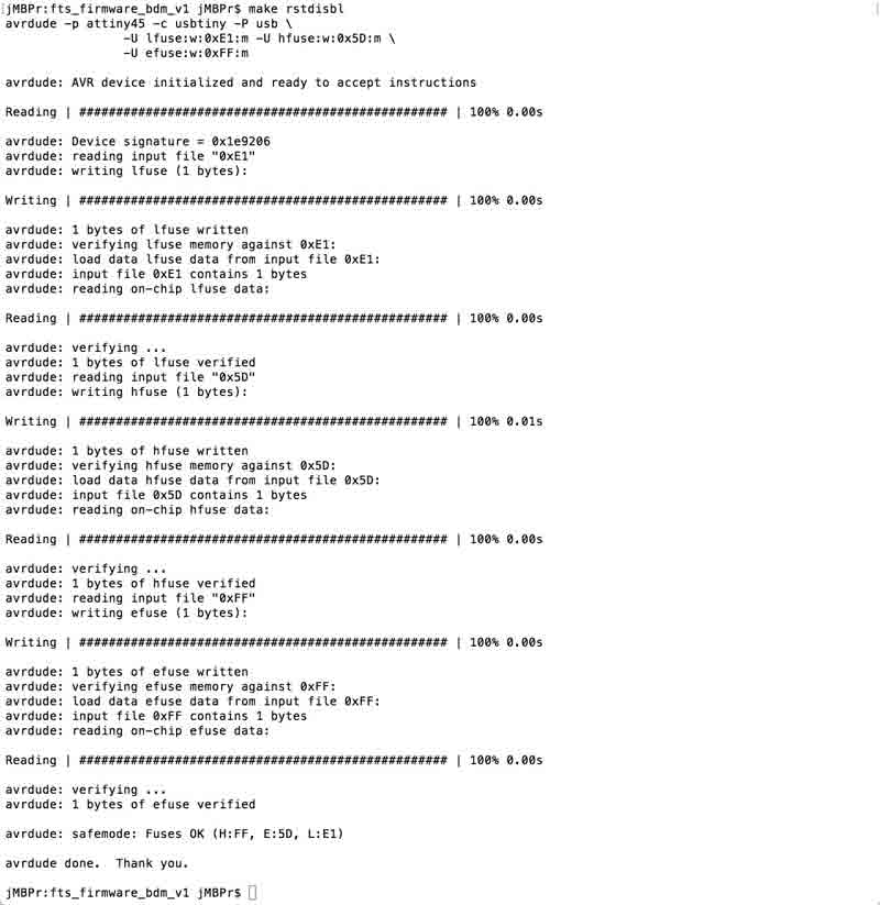
The reset disable command did not work when the programmer was plugged into an USB port on my computer. When I connected it to a port on an adjacent computer, the command worked.
Second, remove the bridge on the solder jumper. I did this by reheating the solder with a clean iron, which visually removed enough solder to disconnect the two sides. Then I double checked with a multimeter.
I will post links to resources I have found helpful here.
Share this post...
« Previous post :: Performance testing MakerBot Replicator II
The lab has a many 3D printers. I started with the MakerBot Replicator 2, which is a material extrusion printer which only uses Polylactic acid (PLA) plastic. "PLA is a biodegradable and bioactive thermoplastic aliphatic polyester derived from renewable resources, such as corn starch (in the United States and Canada), tapioca roots, chips or starch (mostly in Asia), or sugarcane (in the rest of the world)." Wikipedia The first operations are testing the limitations of the machine. ZhaoWei and I tested two models. The first, Zhaowei had on hand giving us time to draw the second while the machine printed....
Next post :: Stuffing a circuit board »
Freshly produced PCB in hand, it is now time to solder the electronic components. Soldering is tricky. Repetition is key. I am beginning to find an effective method varying my practice, trial and error. This is a road map of component placement from the FabTinyISP page. First, gather the components, or do not. I soldered two boards. The first, I gathered everything beforehand, the second time I grab componenets from their storage as I went along. Whatever, both worked. Just be careful not to lose any or return to the wrongly marked storage. The microcontroller and diode components are directional;...