Tags
Embedded programming
- Environmental monitoring with online data logging to Thingsv
- Grow monitors | What watches the watchers?
- LCD x Arduino
- Programming "Hello to the World" with C
- Breathing light : An arduino experiment
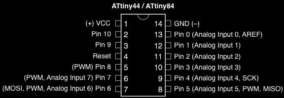
- Datasheet Atmel ATtiny24/44/84
- Echo : Programming.c
- Programming a programmer
- Arduino IDE, introduction
2017 Feb 25
#coding
#microCode
This is Arduino:
- a family of open-source, programmable Atmel microcontroller-based boards
- an abstraction on top of standard C syntax and libs
- a cross-platform IDE
- a bootloader that can upload code without a hardware programmer
- a micro-USB port to plug into the computer, digital/analog input/output pins, a separate power jack, an ISP header, and a reset button
For my purposes today, I will be using the Arduino IDE, an application written in Java in combination with my own fabbed TinyISP. In my limited experience, it is quite similar to Processing. (Unfortunately, I have forgotten everything else about Processing.) Programs may be written in any programming language for a compiler that produces binary machine code for the target processor (wikipedia).
I will be using Arduino 1.8.0. You can find it online with something called google. If you are not using an Arduino AVR board, you will need to add support for non Arduino boards. Here is an unofficial list of 3rd party boards support urls github. You can start there. In my case, I am using this ATtiny44 board. Here is the appropriate URL (as of today):
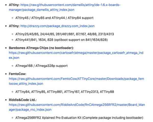
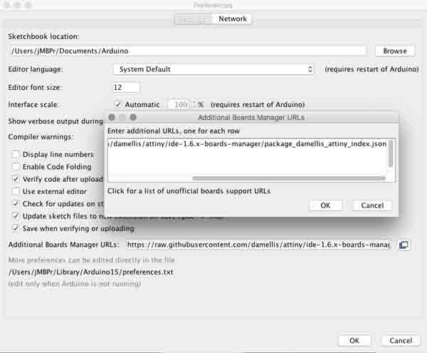
Copy the URL into the Arduino application's board manager. File>Preferences "Additional Boards Manager URLs".
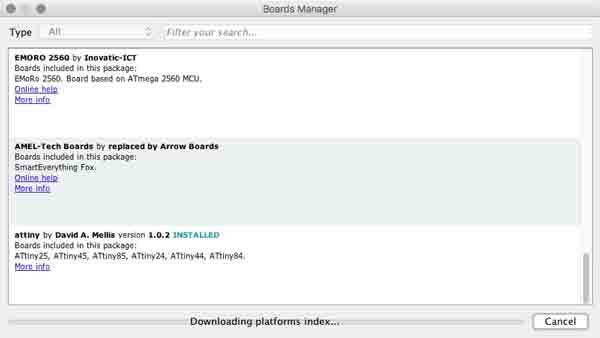
From Tools>Board>Boards Manager... Find the corresponding entry for the board you added and click the install button. Arduino will download the stuff it needs to work with your board.
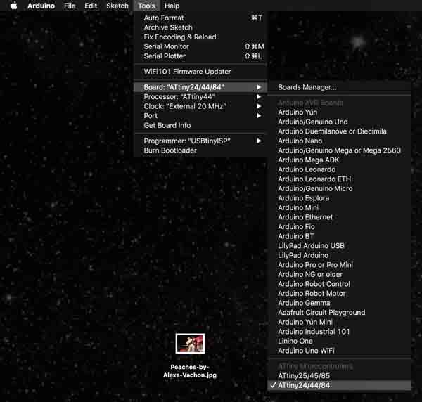
Then within the Tools menu, specify your board, processor, clock and programmer. For my board in the same order:
- ATtiny24/44/84
- ATtiny44
- External 20 MHz
- USBtinyISP
One last step before coding for your board. You will need to translate your microcontroller pin-outs to Arduino friendly speak. Google is your friend. For instance the ATtiny44 pin 6 needs to be designated as Pin 7 in Arduino. Pin 6 (Arduino 7) is the location of my LED and Pin 10 (Arduino 3) my switch.
According to High-Low Tech these Arduino commands are supported by the ATTiny44:
- pinMode()
- digitalWrite()
- digitalRead()
- analogRead()
- analogWrite()
- shiftOut()
- pulseIn()
- millis()
- micros()
- delay()
- delayMicroseconds()
- SoftwareSerial
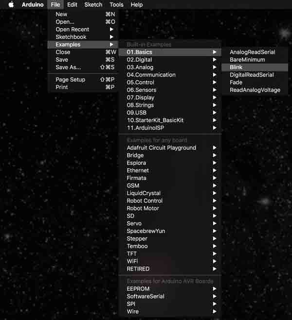
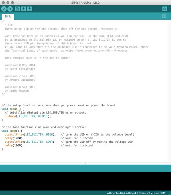
The Arduino application is packaged with some simple example sketches which are great for a quick start with your board. Go to File>01.Basics>Blink
The programming window will open with Blink. Super!
The setup function is called just once when the sketch is loaded and/ or after a restart or power-up (not the mushroom variety of power-ups). This area is for loading libraries, initializing variables, input and output pin modes, etc.
void setup() {
pinMode(LED_BUILTIN, OUTPUT);
}
Following the setup, the loop is the main program which will run FOREVER. Or, until the board is reprogrammed or powered off. The program runs sequentially. First, the LED is turned on. Then the microcontroller is told to hold tight for a timed interval, here, one second. After, that interval, turn the LED off and wait another time interval. Repeat. That means, return to the first line of the loop, and work through the commands again. And again. Again. Again!
void loop() {
digitalWrite(LED_BUILTIN, HIGH);
delay(1000);
digitalWrite(LED_BUILTIN, LOW);
delay(1000);
}
One problem though, the "LED_BUILTIN" refers to an Arduino on-board LED, not my custom board. I need to specify my LED pin 6 (Arduino 7). I can do this by changing the three "LED_BUILTIN" locations to "7". Or, I could specify an integer, the primary data-type for number storage and change the "LED_BUILTIN" to my integer variable name. In this syntax, you can see the structure. "int" tells Arduino this is an integar. This needs to be written exactly as so. "var" is your integar variable name and "val" is the value you assign to this variable.
int var = val;
So in my case it will be written:
const int ledPin = 7;
I will write that somewhere above the void setup and then change "LED_BUILTIN" to "ledPin", my integar value. I added the "const" keyword, meaning constant, because this is an integar that never changes.
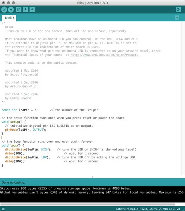
With the fabISP, the ATTiny44 board and your computer interconnected, press the arrow button to load the program to the ATTiny44. And, I have a blinking LED! Believe me, it is blinking. Wait for it.

Unfortunately, the LED is blinking on an estimated 8 second delay instead of the intended 1 second. Perhaps there is a necessary conversion for the 20MHz clock speed with the ATtiny44 using Arduino, my confusion over proper conversion of the delay(time) and 20MHz CPU speed, a calibration between the external resonator and the ATtiny44, or confusion with the clock speed / clock prescaler. I changed the delays to 100 and the LED began blinking at nearly one second on, one second off. I tried adding some code from the ATMEL datasheet (page 30) into my Arduino sketch to adjust the clock prescaler (haha): nothing. Shooting in the dark here.
const int ledPin = 7;

void setup() {
pinMode(LED_BUILTIN, OUTPUT);
}

void loop() {
digitalWrite(LED_BUILTIN, HIGH);
delay(100);
digitalWrite(LED_BUILTIN, LOW);
delay(100);
}
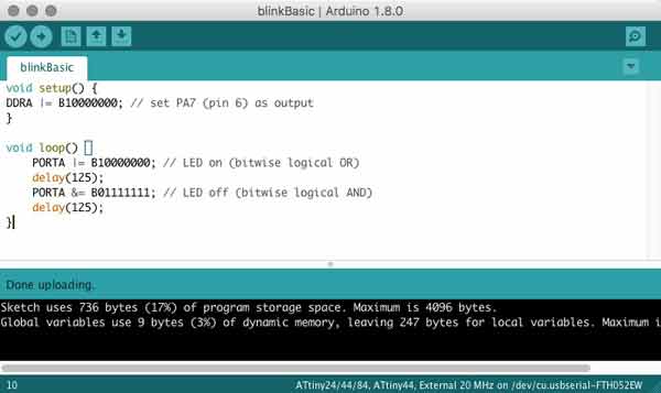
Thanks to Karsten Nebe, this code directly manipulates the registers and is more efficient. The delays set to 125 makes for 1 second blinky.
void setup() {
DDRA |= B10000000; // set PA7 (pin 6) as output
}

void loop() {
PORTA |= B10000000; // LED on (bitwise logical OR)
delay(125);
PORTA &= B01111111; // LED off (bitwise logical AND)
delay(125);
}
I will post links to resources I have found helpful here.
Share this post...
« Previous post :: Milling a circuit board
The PCB is composed of a thin layer of copper, measuring in just microns of thickness, laminated onto FR1, phenolic paper. The pattern of copper connects a series of electronic components with electricity. If any unintentional connections are made, the whole system may be fried. While in subsequent posts, I will explore designing the etching patterns, this time around, I am using an open-source project developed in the FabLab ecosystem: the FabTinyISP version of an AVR ISP programmer/board. You can download the same PNG files I used for the traces and the board outline and read detailed build instruction on...
Next post :: Performance testing MakerBot Replicator II »
The lab has a many 3D printers. I started with the MakerBot Replicator 2, which is a material extrusion printer which only uses Polylactic acid (PLA) plastic. "PLA is a biodegradable and bioactive thermoplastic aliphatic polyester derived from renewable resources, such as corn starch (in the United States and Canada), tapioca roots, chips or starch (mostly in Asia), or sugarcane (in the rest of the world)." Wikipedia The first operations are testing the limitations of the machine. ZhaoWei and I tested two models. The first, Zhaowei had on hand giving us time to draw the second while the machine printed....