2017 Feb 25
#print3d
#model3d
#addFab
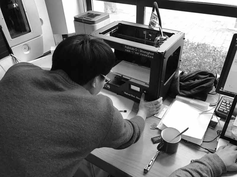
The lab has a many 3D printers. I started with the MakerBot Replicator 2, which is a material extrusion printer which only uses Polylactic acid (PLA) plastic. "PLA is a biodegradable and bioactive thermoplastic aliphatic polyester derived from renewable resources, such as corn starch (in the United States and Canada), tapioca roots, chips or starch (mostly in Asia), or sugarcane (in the rest of the world)." Wikipedia The first operations are testing the limitations of the machine.
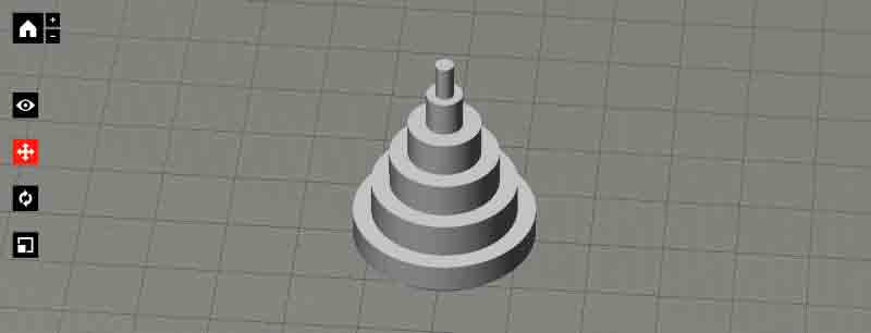
ZhaoWei and I tested two models. The first, Zhaowei had on hand giving us time to draw the second while the machine printed. The simple test model would give us some indication of tolerances and accuracy.
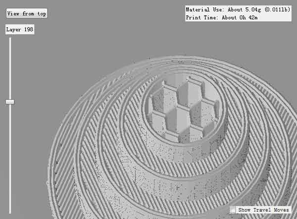
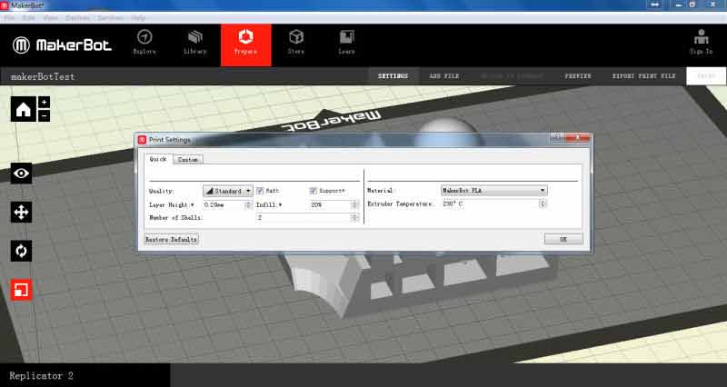
We used the MakerBot's print software. There are many available 3D print applications, some of which I intend to test in the next few days. The application accepts STL files, which are commonly available for export from 3D applications. STL files can only be mesh type models, not nurbs. This shows the intended paths of the machine head as it deposits layers of material and a hex infill, which can be activated and controlled for density within the application. The infill will help strengthen the model while limiting the density of the unseen material. For this model, infill was set to 10%.
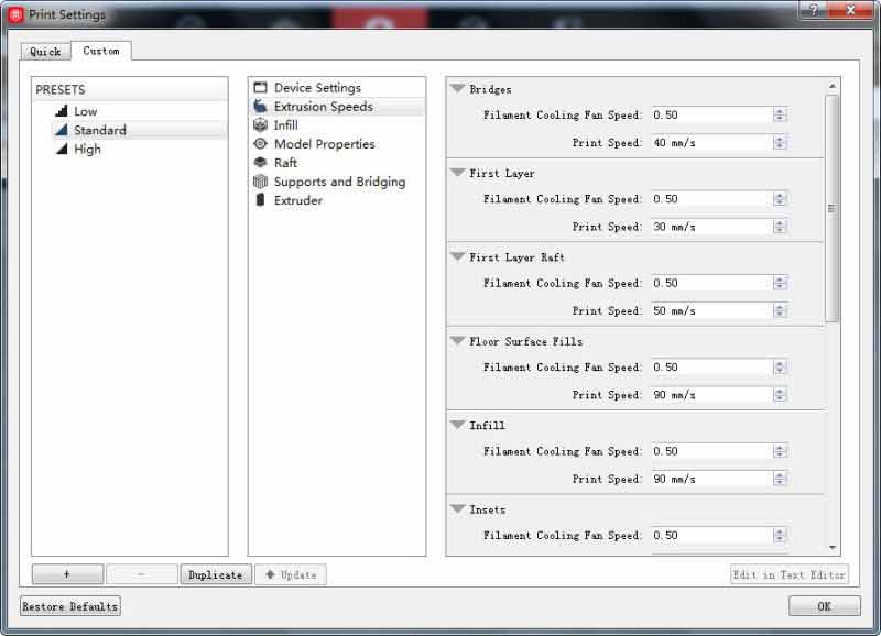
Following are screenshots of our settings. Number of shells refers to the amount of offset layers from the walls of the model. Each offset is 0.40mm thick. This model used 2. The MakerBot can extrude a raft, which is a small bit of disposable material intended to level the material bed and help prevent a model from snapping when removing it from the acrylic bed.
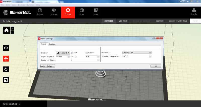
Files are exported from the MakerBot application, saved onto a flash memory card and loaded into the machine. The machine bed raises to the top and the printer lays down the PLA plastic, only layer at a time. This time, each layer height was set to 0.10mm.
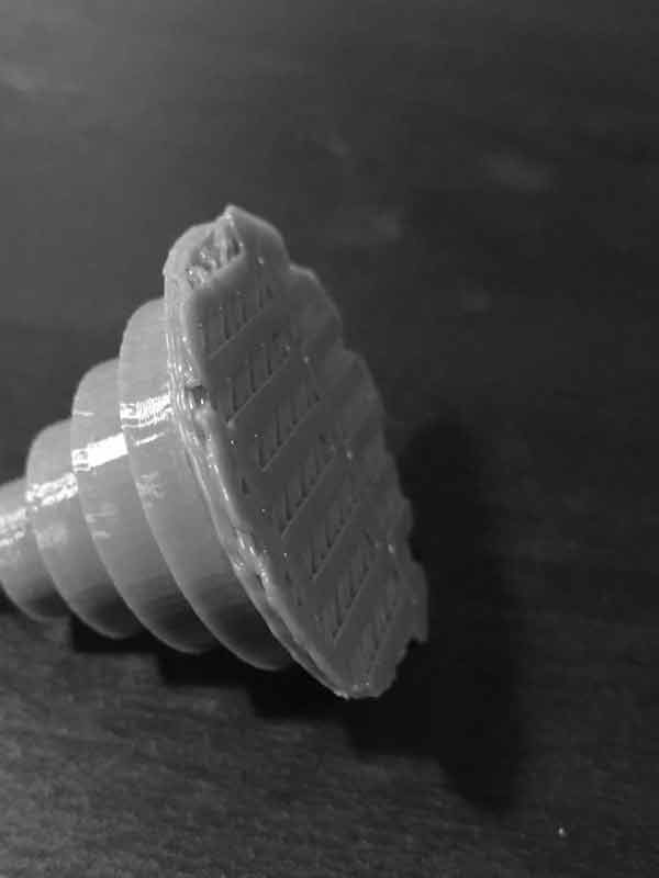
The upper most two levels of this cake were too small for the printer. Likely, the printer was moving too fast for such a small area, not permitting proper material cooling time.
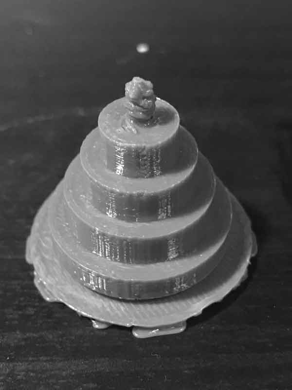
The bottom of this model is the aforementioned raft. I found the easiest way to remove this was with a plaster knife. Slowly work the edge between the raft and the thing until the two release.
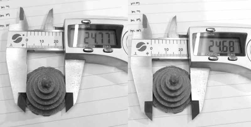
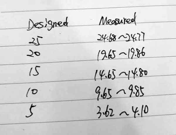
Aside from the problems with the top of the model, we found some inconsistencies in circle diameters on two axes. Measurements are shown below.
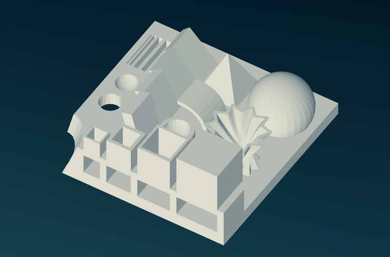
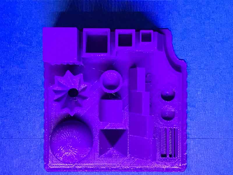
The second test was designed in Autodesk Maya to test a number of printing conditions including rounded objects (sphere), twisty cornery objects, standard dim objects, hollow objects from the top and side, angles, cantilevers, etc. All the tests were anchored to one platform making it easier to keep them all together.

We used an infill of 20% and layer height of 0.20mm. The time estimate was about four hours for this test. The dimensions of the bounding box are 90mm x 90mm x 39mm. If the setting for layer height had been the same as the previous test, 0.10mm, the print time would have doubled.
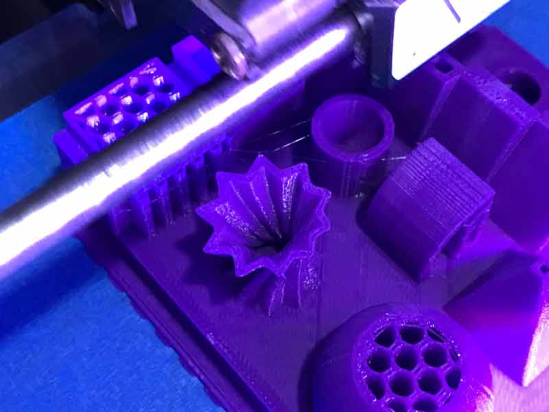
Midway through the print, we can see the infill and offset thicknesses. Also, some temporary scaffolding was built by the printer under the cantilevers.
On first glance, the print closely resembles the original STL file...
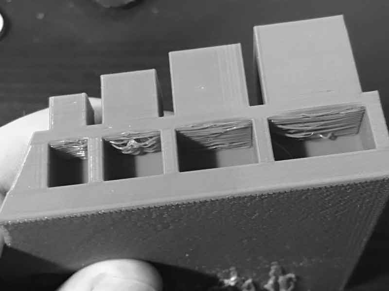
The "ceiling" of these chambers delaminated before the PLA plastic was able to congeal.
An extra line of missing material was printed here. The measurements for these alternating zones from left to right: Hole: 0.50mm, 0.80mm, Hole: 1.00mm, 1.20mm, Hole: 2.00mm, 1.60mm, Hole: 4.00mm.

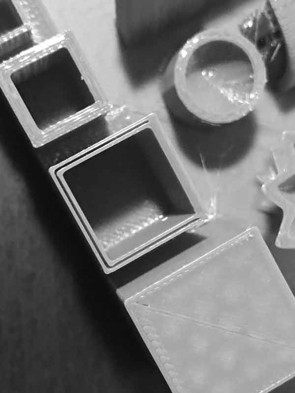
The wall of this box printed with missing material. The distance from the outside to inside surface (wall thickness) was 1.20mm. Again, the printer made a mistake with 1.20mm thickness which is a multiple of its 0.40mm thickness head.
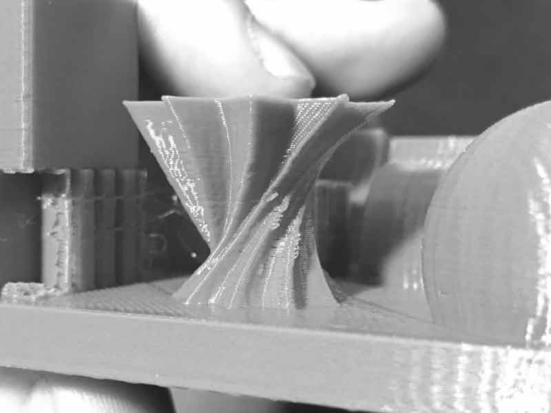
Along the folds of this twisty thing, some fuzziness occurred.
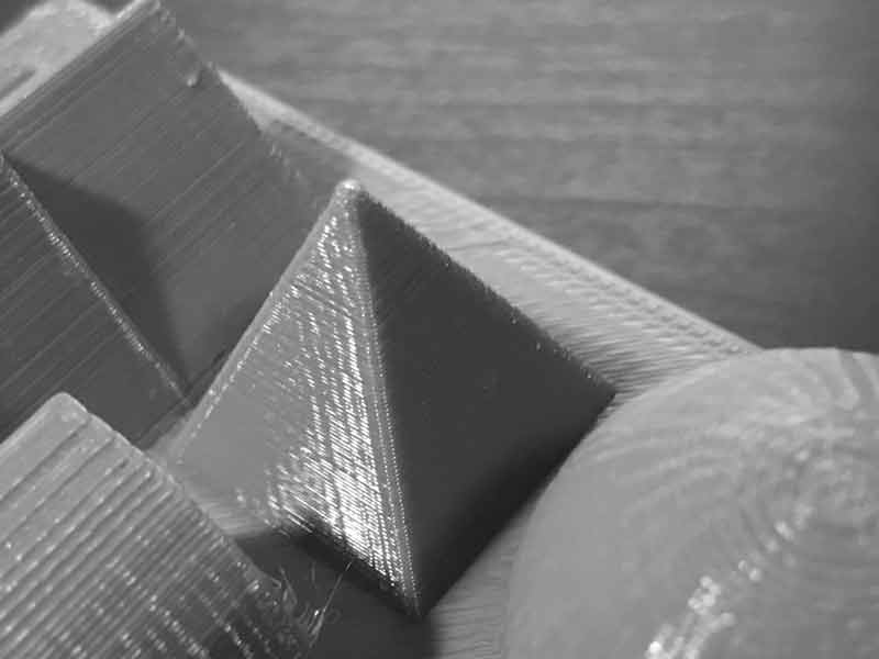
Unlike the first test, this pyramid came to a point. This may be attributable to the fact the machine head had to work through all the other zones on each layer before returning to add the next layer to the pyramid. As such, each layer had ample time to set.
I will post links to resources I have found helpful here.
Share this post...
« Previous post :: Arduino IDE, introduction
This is Arduino: a family of open-source, programmable Atmel microcontroller-based boards an abstraction on top of standard C syntax and libs a cross-platform IDE a bootloader that can upload code without a hardware programmer a micro-USB port to plug into the computer, digital/analog input/output pins, a separate power jack, an ISP header, and a reset button For my purposes today, I will be using the Arduino IDE, an application written in Java in combination with my own fabbed TinyISP. In my limited experience, it is quite similar to Processing. (Unfortunately, I have forgotten everything else about Processing.) Programs may be...
Next post :: Programming a programmer »
An in-circuit serial programmer (ICSP) is capable of programming microcontrollers on various boards with only a universal serial bus (USB) cable and 6-pin insulation-displacement contact (IDC) to 6-pin IDC cable. The ICSP vastly simplifies what would otherwise be an expensive and laborious process across different chip types. First I installed Crosspack on my mac. Crosspack is a development environment for AVR microcontrollers and necessary to give the terminal app capability for the upcoming task. Next, from the FabTinyStar page, I downloaded the firmware source code. I added a link here as well. You can open the Makefile with a neutral...