Tags
#electronics
#coding
#microCode
Embedded programming
- Environmental monitoring with online data logging to Thingsv
- Grow monitors | What watches the watchers?
- LCD x Arduino
- Programming "Hello to the World" with C
- Breathing light : An arduino experiment
- Datasheet Atmel ATtiny24/44/84
- Echo : Programming.c
- Programming a programmer
- Arduino IDE, introduction
2017 Mar 22
#electronics
#coding
#microCode
I now have a grasp of making slight adjustments to code and uploading code to my board. Now that I have a little taste, I want more, so I imagined a simple idea to go a step beyond the tutorials and example codes. An interesting thing to me about coding is how the process is not linear, like what can often happen in other design fields. I can start layering in code and then make a little game of optimizing that code for editing, total number of executions, or number of lines, for instance. In fact, speaking of games, I am a fan. And there are many games available online for learning code in many different languages. Although I did not have much time to explore them all, I will probably come back to some in my free time. One multiplatform (including iOS) game: Human Resource Machine helped prime my brain for thinking code. The diffculty ramps up nicely (which translates into increasingly challenging coding) and it was fun!
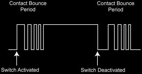
Next, I dove into this tutorial to learn about using a switch, which was absent up to this point, Pulse Width Modulation (PWM) and compensating for switch bouncing (more on these later).
When the button is pressed, there may be some bouncing that occurs within. These are tiny parts and the bouncing may only occur over fractions of a second. To the MCU, however, that might be what we perceive as days. This diagram shows the effect. Your code can include a configurable delay in reading the switch to bypass the bouncing period after pressing it.
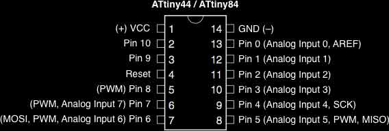
From Arduino: "Pulse Width Modulation, or PWM, is a technique for getting analog results with digital means. Digital control is used to create a square wave, a signal switched between on and off." I went back to the ATtiny datasheet and sure enough, Pin 6, the location of my LED, has PWM.
I started by following along with the tutorial with some small mods. I think it is good to get a sense of how my process of building a code happens, so I will show some steps. Not interested? Skip to the bottom of this section. This first sketch turns on the LED when the switch is engaged and off when it is released.
const int switchPin = 3;
const int ledPin = 7;

void setup() {
pinMode(switchPin, INPUT);
pinMode(ledPin, OUTPUT);
}

void loop() {
if (digitalRead(switchPin) == HIGH)
{
digitalWrite(ledPin, HIGH);
}
else
{
digitalWrite(ledPin, LOW);
}
}
The next iteration changed the action to flipping the LED on and off with button presses, like a light switch. Here, you can see a couple of booleans are added. A boolean holds one of two values, ie. true or false. In the loop, if the switch is pressed which is verfied against the previous switch state, then flip the ledState (this is the function of the ! mark) and then change the lastSwitch back to high to reset the conditions for the if / else statement. And write the change to the ledState, change it to true for on, false for off.
const int switchPin = 3;
const int ledPin = 7;
boolean lastSwitch = LOW;
boolean ledState = false;

void setup() {
pinMode(switchPin, INPUT);
pinMode(ledPin, OUTPUT);
}

void loop() {
if (digitalRead(switchPin) == HIGH && lastSwitch == LOW)
{
ledState = !ledState;
lastSwitch = HIGH;
}
else
{
lastSwitch = digitalRead(switchPin);
}
digitalWrite(ledPin, ledState);
}
This iteration adds a debounce boolean to negate signal noise in the button presses. Basically, if the button state seems to change, wait a moment and verify the change. Adjust the delay according to its effectiveness. Then the loop incorporates the debounce boolean.
const int switchPin = 3;
const int ledPin = 7;
boolean lastSwitch = LOW;
boolean currentSwitch = LOW;
boolean ledState = false;

void setup() {
pinMode(switchPin, INPUT);
pinMode(ledPin, OUTPUT);
}

boolean debounce(boolean last)
{
boolean current = digitalRead(switchPin);
if (last != current)
{
delay(5);
current = digitalRead(switchPin);
}
return current;
}

void loop() {
currentSwitch = debounce(lastSwitch);
if (lastSwitch == LOW && currentSwitch == HIGH)
{
ledState = !ledState;
}
lastSwitch = currentSwitch;
digitalWrite(ledPin, ledState);
}
This version drops the ledState boolean, for an analog brightness. Everytime the button is pressed, the brightness of the light increases slightly. Until, that brightness number exceeds 255, when it is set back to 0 (off). That is the PWM at work.
const int switchPin = 3;
const int ledPin = 7;
boolean lastSwitch = LOW;
boolean currentSwitch = LOW;
int ledLevel = 0;

void setup() {
pinMode(switchPin, INPUT);
pinMode(ledPin, OUTPUT);
}

boolean debounce(boolean last)
{
boolean current = digitalRead(switchPin);
if (last != current)
{
delay(5);
current = digitalRead(switchPin);
}
return current;
}

void loop() {
currentSwitch = debounce(lastSwitch);
if (lastSwitch == LOW && currentSwitch == HIGH)
{
ledLevel = ledLevel + 51;
}
lastSwitch = currentSwitch;

if (ledLevel > 255) ledLevel = 0;
analogWrite(ledPin, ledLevel);
}
I started trying to get the light to go through a series of brightness changes each time the button was pressed (rather than one change per press, several changes per press). After some trial and error, I moved the analogWrite function into the if statement, added some delays and went to work. This time with each button press the light turns off and then slowly increases in brightness up to full brightness and remains on.
const int switchPin = 3;
const int ledPin = 7;
boolean lastSwitch = LOW;
boolean currentSwitch = LOW;
int ledLevel = 0;

void setup() {
pinMode(switchPin, INPUT);
pinMode(ledPin, OUTPUT);
}

boolean debounce(boolean last)
{
boolean current = digitalRead(switchPin);
if (last != current)
{
delay(5);
current = digitalRead(switchPin);
}
return current;
}

void loop() {
currentSwitch = debounce(lastSwitch);
if (lastSwitch == LOW && currentSwitch == HIGH)
{
ledLevel = 0;
analogWrite(ledPin, ledLevel);
delay(125);
ledLevel = ledLevel + 51;
analogWrite(ledPin, ledLevel);
delay(125);
ledLevel = ledLevel + 51;
analogWrite(ledPin, ledLevel);
delay(125);
ledLevel = ledLevel + 51;
analogWrite(ledPin, ledLevel);
delay(125);
ledLevel = ledLevel + 51;
analogWrite(ledPin, ledLevel);
delay(125);
ledLevel = ledLevel + 51;
analogWrite(ledPin, ledLevel);
}
lastSwitch = currentSwitch;

if (ledLevel > 255) ledLevel = 0;
}
Next, I tried to get the light to increase in brightness from an off state to a full state and then back down. I added some variables for the brightness step and timer. Still, if I want to make any changes its a lot of work...
const int switchPin = 3;
const int ledPin = 7;
boolean lastSwitch = LOW;
boolean currentSwitch = LOW;
int ledLevel = 0;
int timer = 125;
int ledChange = 51;

void setup() {
pinMode(switchPin, INPUT);
pinMode(ledPin, OUTPUT);
}

boolean debounce(boolean last)
{
boolean current = digitalRead(switchPin);
if (last != current)
{
delay(5);
current = digitalRead(switchPin);
}
return current;
}

void loop() {
currentSwitch = debounce(lastSwitch);
if (lastSwitch == LOW && currentSwitch == HIGH)
{
ledLevel = ledLevel + ledChange;
analogWrite(ledPin, ledLevel);
delay(timer);
ledLevel = ledLevel + ledChange;
analogWrite(ledPin, ledLevel);
delay(timer);
ledLevel = ledLevel + ledChange;
analogWrite(ledPin, ledLevel);
delay(timer);
ledLevel = ledLevel + ledChange;
analogWrite(ledPin, ledLevel);
delay(timer);
ledLevel = ledLevel + ledChange;
analogWrite(ledPin, ledLevel);
delay(timer);
ledLevel = ledLevel - ledChange;
analogWrite(ledPin, ledLevel);
delay(timer);
ledLevel = ledLevel - ledChange;
analogWrite(ledPin, ledLevel);
delay(timer);
ledLevel = ledLevel - ledChange;
analogWrite(ledPin, ledLevel);
delay(timer);
ledLevel = ledLevel - ledChange;
analogWrite(ledPin, ledLevel);
delay(timer);
ledLevel = ledLevel - ledChange;
analogWrite(ledPin, ledLevel);
}
lastSwitch = currentSwitch;
}
So I started to look around for a (my words) repeat something until something command. For that, I found the while statement. While the light is powered lower than my ledMax integar, add power at my timing. Once the ledMax is surpassed, reduce the power to zero at my timing. It is more convenient for me to ask the chip to find its own ledMax based on the ledChange interval. It mostly works, but sometimes the light flickers at its brightest.
const int switchPin = 3;
const int ledPin = 7;
boolean lastSwitch = LOW;
boolean currentSwitch = LOW;
int ledLevel = 0;
int timer = 25;
int ledChange = 5;
int ledMax = 0;

void setup() {
pinMode(switchPin, INPUT);
pinMode(ledPin, OUTPUT);
while(ledMax <= 255) {
ledMax = ledMax + ledChange;
}
}

boolean debounce(boolean last)
{
boolean current = digitalRead(switchPin);
if (last != current)
{
delay(5);
current = digitalRead(switchPin);
}
return current;
}

void loop() {
currentSwitch = debounce(lastSwitch);
if (lastSwitch == LOW && currentSwitch == HIGH)
{
while(ledLevel < ledMax) {
ledLevel = ledLevel + ledChange;
analogWrite(ledPin, ledLevel);
delay(timer);
}
while(ledLevel > 0) {
ledLevel = ledLevel - ledChange;
analogWrite(ledPin, ledLevel);
delay(timer);
}
}
lastSwitch = currentSwitch;
}
Because, I was using poor math. I made some adjustments to the ledMax integar and it seems to be working now. Press the switch, and the light ramps up and ramps back down according to a specified timing and change interval.
const int switchPin = 3;
const int ledPin = 7;
boolean lastSwitch = LOW;
boolean currentSwitch = LOW;
int ledLevel = 0;
int timer = 50;
int ledChange = 25;
int ledMax = 0;

void setup() {
pinMode(switchPin, INPUT);
pinMode(ledPin, OUTPUT);
while(ledMax < 255) {
ledMax = ledMax + ledChange;
}
ledMax = ledMax -ledChange - 1;
}

boolean debounce(boolean last)
{
boolean current = digitalRead(switchPin);
if (last != current)
{
delay(5);
current = digitalRead(switchPin);
}
return current;
}

void loop() {
currentSwitch = debounce(lastSwitch);
if (lastSwitch == LOW && currentSwitch == HIGH)
{
while(ledLevel < ledMax) {
ledLevel = ledLevel + ledChange;
analogWrite(ledPin, ledLevel);
delay(timer);
}
while(ledLevel > 0) {
ledLevel = ledLevel - ledChange;
analogWrite(ledPin, ledLevel);
delay(timer);
}
}
lastSwitch = currentSwitch;
}
Then for fun, I removed the switch functionality completely for a more lifelike blinking sketch.
const int ledPin = 7;
int ledLevel = 0;
int timer = 50;
int ledChange = 25;
int ledMax = 0;


void setup() {
pinMode(ledPin, OUTPUT);
while(ledMax < 255) {
ledMax = ledMax + ledChange;
}
ledMax = ledMax -ledChange - 1;
}

void loop() {
while(ledLevel < ledMax) {
ledLevel = ledLevel + ledChange;
analogWrite(ledPin, ledLevel);
delay(timer);
}
while(ledLevel > 0) {
ledLevel = ledLevel - ledChange;
analogWrite(ledPin, ledLevel);
delay(timer);
}
}
It could be fun to see if I can make the breathing like function turn on with the switch and off without and/ or to add some math induced variables to the change and timing intervals to make it even more wild.
Download project files
I will post links to resources I have found helpful here.
Share this post...
« Previous post :: Datasheet Atmel ATtiny24/44/84
Datasheets are hardcore product manuals for instructing makers on how to integrate specific products (ie electronic components) into systems. Datasheets are typically created by the product manufacturer and include technical and performative characteristics, connectivity information, coding examples, etc. A datasheet for an electronic component, such as an MCU like the ATtiny44, typically contains the following: Feature list and overview Pin configurations and descriptions Timing diagrams Reset and interrupt handling Register description Memories details Input/output informations Clock system Power management Packaging details and configurations and much more! This is the first time I have read a datasheet and I have only...
Next post :: Machine precedents »
Over the past couple months we have been learning to use tools for fabrication and coding. Now, we are faced with the challenge to pull these tools together into a fabbed robot. My initial concept is a Seymour Papert "turtle" inspired drawing robot that can use water to write poetry in Chinese characters on outdoor concrete ground surfaces. First I will survey the drawing bot landscape. Dishu is "earth writing or practicing ephemeral calligraphy on the ground using clear water as ink." The imagined robot would be mobile using legs or wheels, battery-powered, use water through a brush to make...