Tags
dishuBot
2017 Mar 27
#research
#dishuBot
#machine
Over the past couple months we have been learning to use tools for fabrication and coding. Now, we are faced with the challenge to pull these tools together into a fabbed robot. My initial concept is a Seymour Papert "turtle" inspired drawing robot that can use water to write poetry in Chinese characters on outdoor concrete ground surfaces.
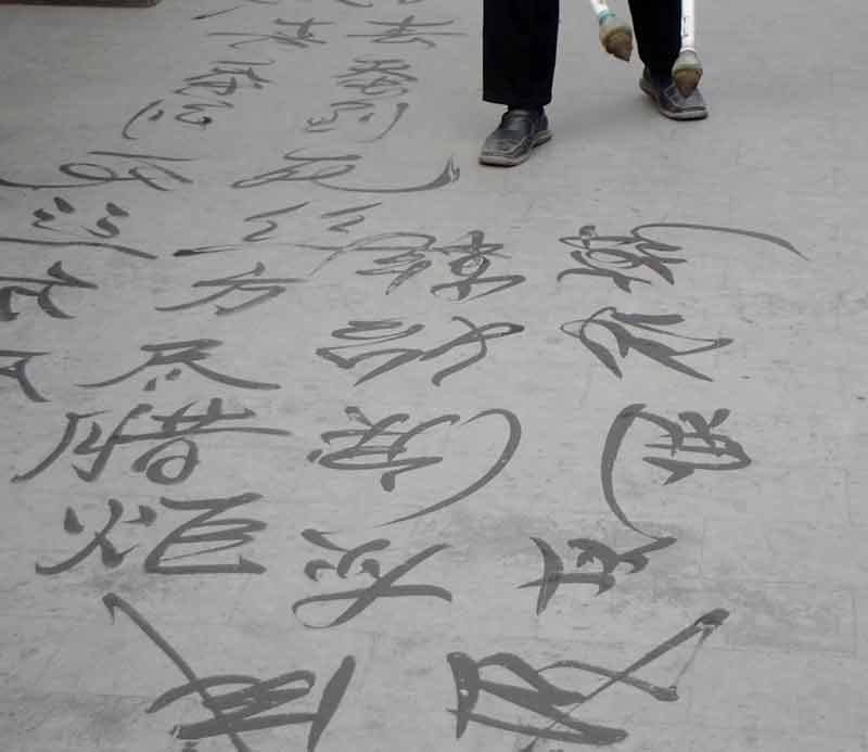
First I will survey the drawing bot landscape. Dishu is "earth writing or practicing ephemeral calligraphy on the ground using clear water as ink." The imagined robot would be mobile using legs or wheels, battery-powered, use water through a brush to make drawings translated through computer-generated code.

The following exercpt is from Francois Chastanet's book: Dishu: Ground Calligraphy in China.
"The endlessly tracing texts composed of «hanzi» signs slowly disappear as water evaporates. This phenomenon, called «dishu», appeared in the beginning of the 1990s in a north Beijing park and soon spread to most major Chinese cities. Based on classic Chinese literature, poetry or aphorisms, these monumental letterings, ranging from static and regular to highly cursive styles, make the whole body break into spontaneous dance and infinite formal renewals. This street calligraphic practice corresponds to both a socializing need and an individual search for self accomplishment or improvement."
Hanzi is typically written from a top to down left to right manner and line thickness is controlled by the force (or speed?) of the brush onto the surface. I think it would be wonderful if the robot is capable of mimicing this sequence and line width control.
The inspiration and direction for this robot comes from Seymour Papert's LOGO "turtle".
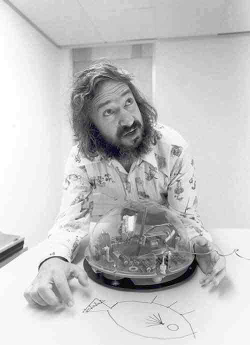
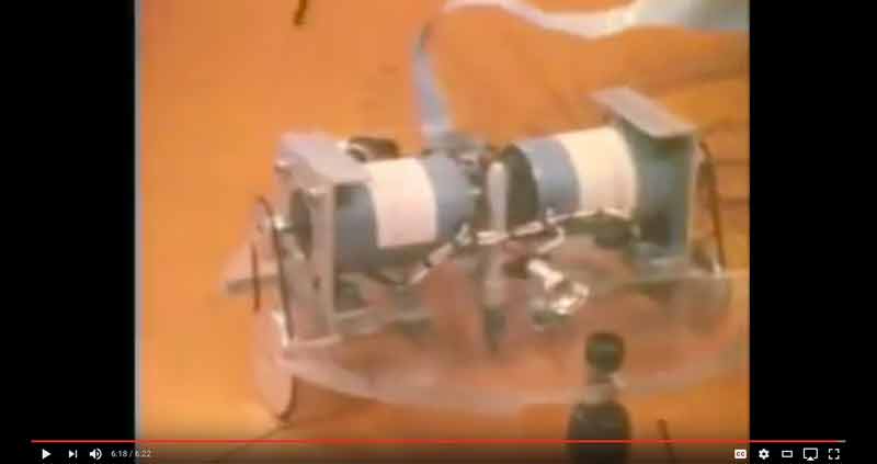
A wonderful television expose Seymour Papert's LOGO and turtle drawing robot. If you can, I recommend listening to something like Radiohead's "Treefingers" or Mum's "Slow Bicycle" while watching the video. It helps direct your mind into the right space.
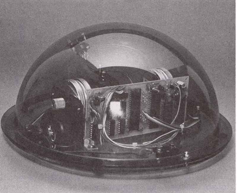
From the video, it is appears this version of the turtle is made of an acryllic base, two wheels individually driven by motors connected via timing belts, two ball bearing casters on the perpendicular axis and a sharpie marker near the center perhaps connected via a servo bracket. Data and power are provided externally via the serial cable. The previous image shows a vaccuum formed plastic globe and some additional finishing materials under the base which gives the robot character.
Design considerations for our Dishu Robot.
- Simple : Easy to build
- Simple : Easy to program
- Capable of operating on outdoor surfaces (cracks, pebbles)
- Battery powered
- Working area size and characteristics
- Wheels do not collide with drawing surface
- Open source
Design components of our Dishu Robot.
- Wheels
- Stepper motors for accurate motion.
- Balance
- Multiple wheels each side?
- Ball bearings for balance?
- Individually controlled for steering
- (advanced)Speed control for variable line thickness
- Effector
- Stabilizer
- Stem diameter adjustment
- Water supply
- Permits movement of brush not to obstruct flow
- (advanced)Pressure sensitivity
- Stage
- Movement
- Support effector
- Frame
- Batteries
- PCBs
- Water
- Code
- Drawing translation computer langauge
- XYZ directives?
- Code to wheel,a
- Code to wheel,b
- Code to stage
- Code to effector
- (advanced)Collision detection sensors
Thoughts on uses.
I think this type of robot could be used for many useful things beyond Dishu. For instance, the robot could draw permanent artistic patterns on floors in paints or inks. It could draw patterns on large stock material for various uses such as construction. Maybe the robot does not use a pen and is instead equipped with a knife for large scale cuttingp applications; maybe it cuts patterns of mega-origami. That could be fun.
Regarding motion.
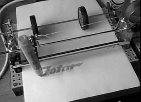
Gears driven by motors. One gear to move the brush holder along an axis and another to move the assembly along the perpendicular axis ala the Itty Bitty Drawing Robot. This could be used to move the brush one one axis independent of the movement of the wheels on another axis.
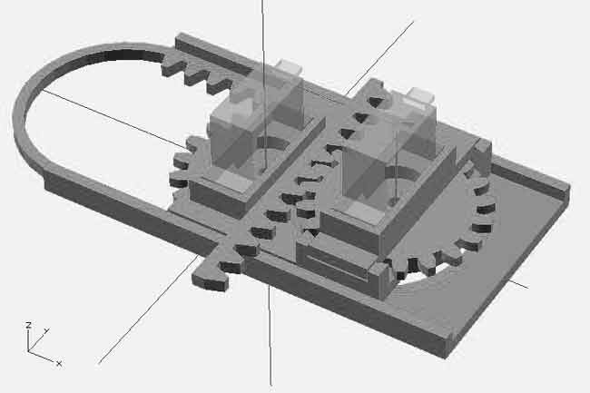
A Gestalt stage, developed by Nadya Peek and James Coleman, used for motion in one direction, while something else, wheels or legs, freely move the robot in the perpendicular direction.
This fabricatable machine by Jens Dyvik with the linear rails, rack, pinion and glide blocks all fabricatable on conventional CNC milling machines. Fantastic.

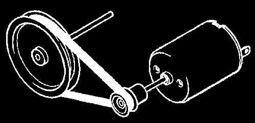
Motors attached directly to wheels. Rubber is added around the outside face of the wheel.
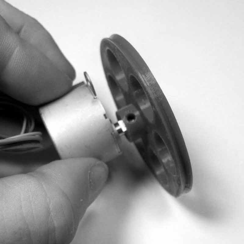
Or motors attached to belts attached to wheels. I think this option might make operation less efficient but looks better. Also, The motor could be positioned with greater freedom in relation to the wheel, whereas the previous option requires the motor to be centered on the wheel. This seems to be the technique used in the LOGO "turtle".
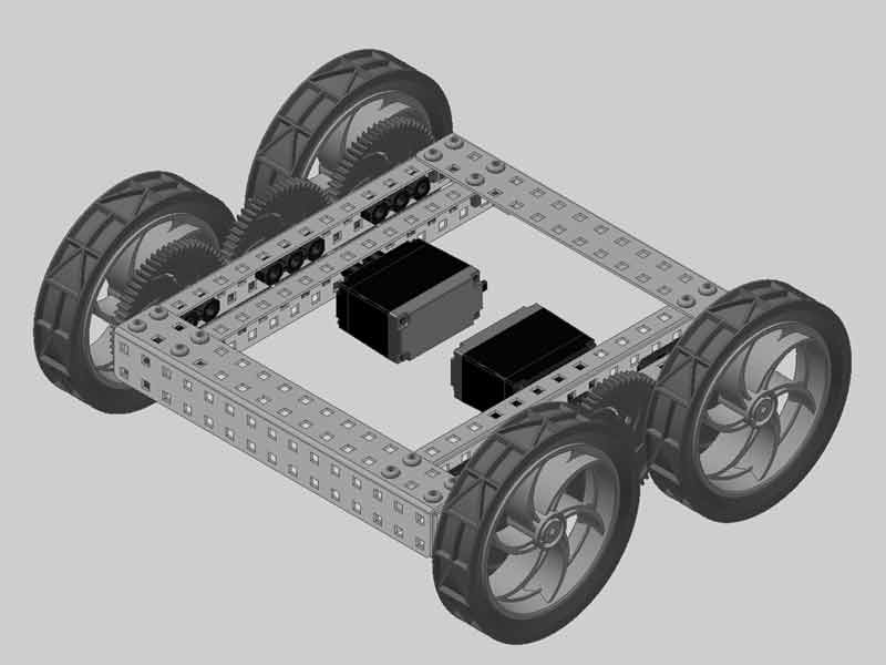
Further, this could be a motorized gear connected to two wheels on each side for balancing the machine. This diagram from this gear train design blogpost displays a [stepper] motorized gear driving two wheels.
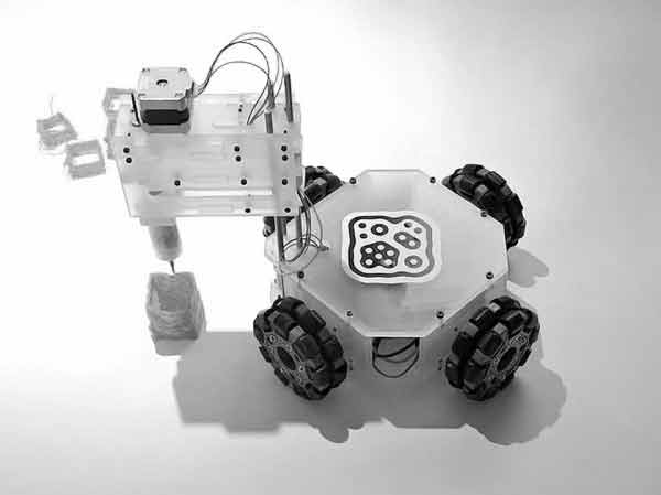
Carmen found this drawbot archetype, 3&Dbot, uses two pairs of wheels oriented to perpendicular axes. Omni-directional wheels are used to permit full motion.
Carmen found this similar execution of splitting the brush and movement axes. However, this robot moves the paper instead of the machine. Our robot is intended to move itself.
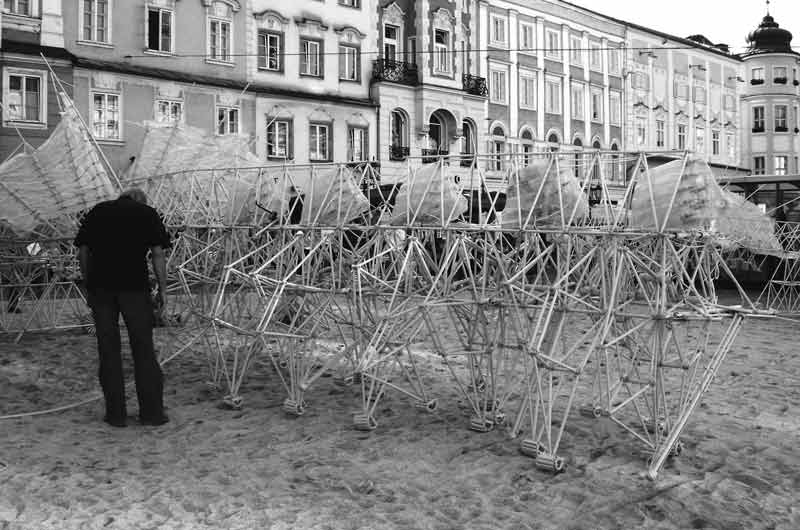
Theo Jensen inspired walking legs. Which, by the way, is infinitely more dynamic and sensational than wheels! Can the movement be discretely controlled by stepper motors? To what increment?
Carmen found this diagram of a large-scale cable camera movement system from a blog entry. One possibility would be to post a tent like structure, connect these cables, and then execute the drawings.
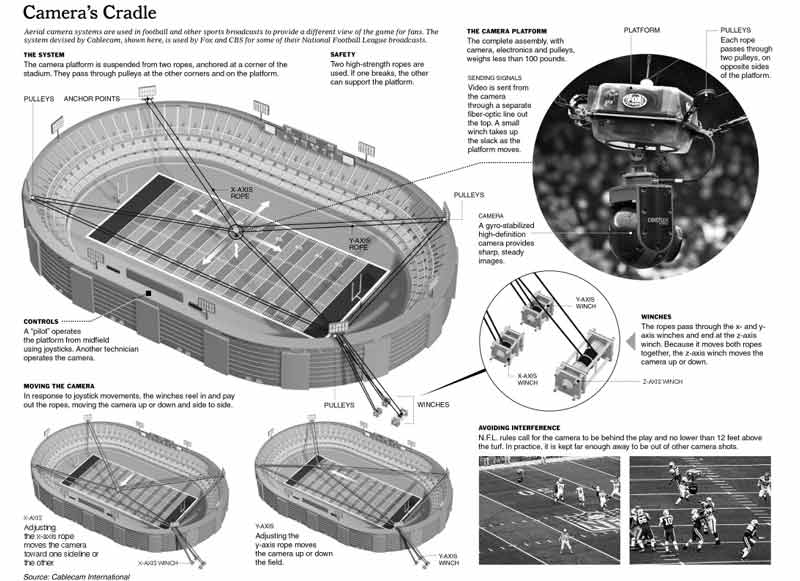
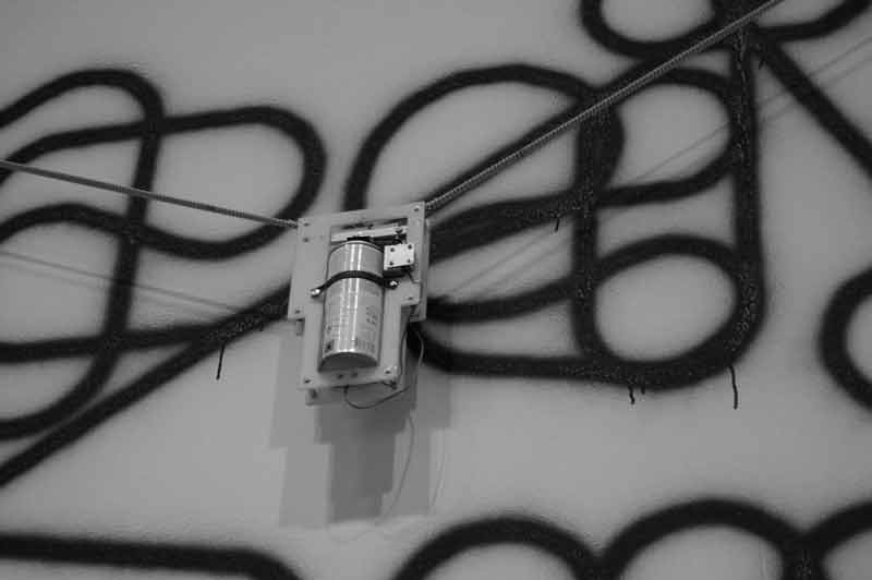
Often considered the first of the hanging wall drawing machine type, Hektor is a machine consisting of two motors, toothed belts and a spray can holder. It is controlled by a software written in Scriptographer running inside of Adobe Illustrator. From the Hektor webpost, "A geometric path-finding algorithm calculates the motion paths required by the fragile mechanical installation to move smoothly and not lose the battle against gravity. The algorithm then translates these paths into rotations of the two stepper motors that position the spray-can, and coordinates the pressing of its nozzle." Between the stadium scale of the Camera's Cradle to the wall scale of Hektor, could a robot draw on a floor surface using a tension system and be mobile with legs or wheels?
About the brush holder and effector.
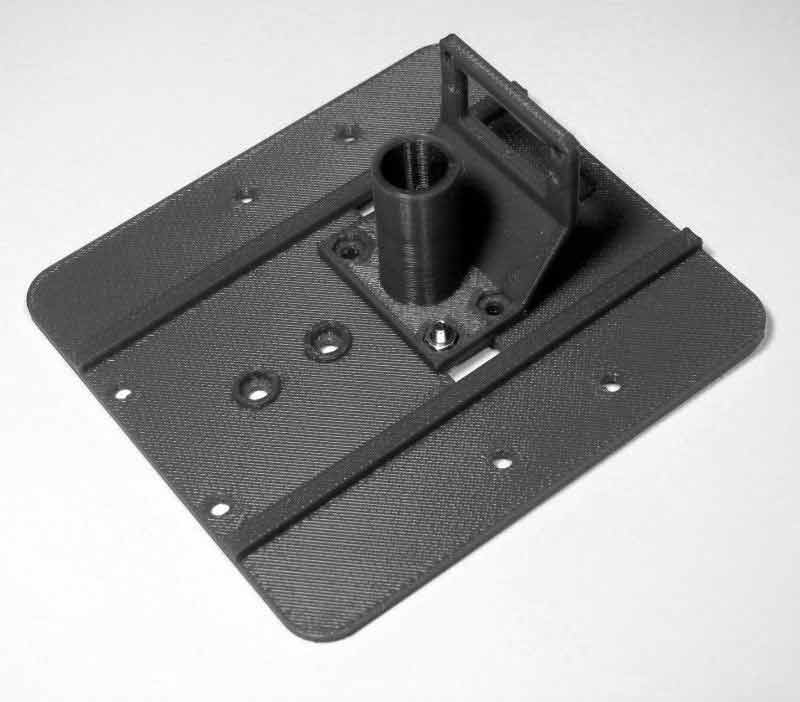
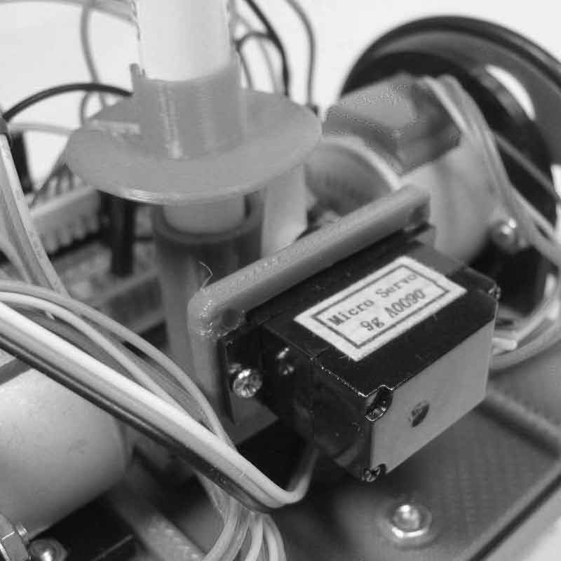
The simplest most widely used variant seems to involve a micro-server that pushes on a sleeve (wrapped around the brush handle) to move the brush onto and away from the surface through an extruded rail. These images are from the Low-cost, Arduino-compatible drawing robot post on instructables. I think one improvement on this design would be to flip the direction of the sleeve so it slides into the rail. This way the two can be calibrated together to help minimize jiggle, while the sleeve is adjustable to multiple brush sizes.
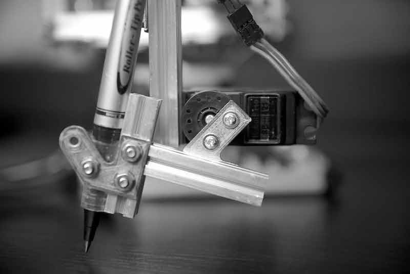
This is a more elegant solution to brush movement found in the "Polar Plotter on Arduino and MakerBeams" project found by Carmen. In this case, the servo has two positions up and down. Could it be modified for pressure variants?
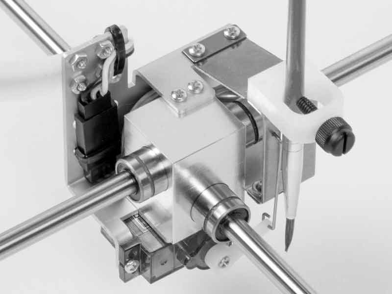
Watercolor Bot has an effector that uses two stressed plastic planes in combination with a servo motor and an adjustable collar (screw). The stress in the plastic helps keep the brush in constant contact with the paper and is located very near the crossing point of the X,Y axes (0,0).
FabAcademy student Keith Tan designed an adjustable end effector with a spring. Rubberbands would also be used.
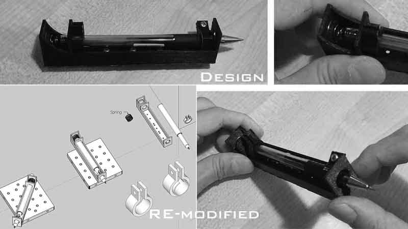
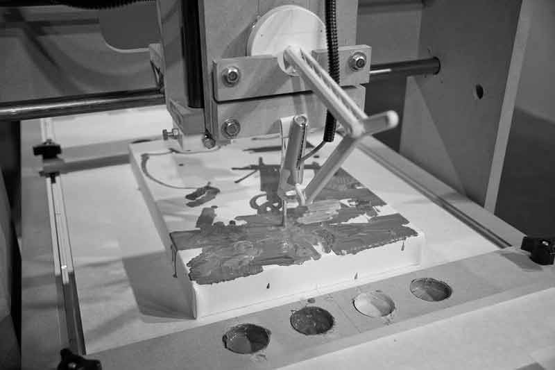
And finally the overkill solution. The entire armature of the Interactive Robotic Painting Machine moves up and down along the vertical axis (relative to drawing plane). This is certainly capable of pressure variance.
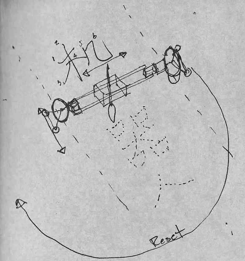
What might it look like?
Despite being crude, these sketches portray an overall strategy for the dishu robot. This first sketch shows the movement systems. The servo controlled brush is connected to a movement axis while the stepper motor controlled wheels operate on another axis. The robot draws characters via a combination of axial movement by the two systems. At the end of a line, the robot swings around by moving one wheel at a greater rate than the other.
A crazy variation on this may be to use walking legs. Also, this sketch at least recognizes the need for water, battery and controller space on the robot. Legs may work better for walking over cracks and small stones common to outdoor floors. It seems difficult to implement though.
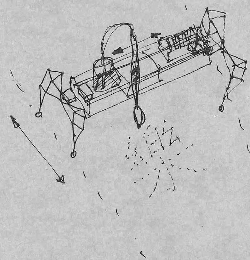
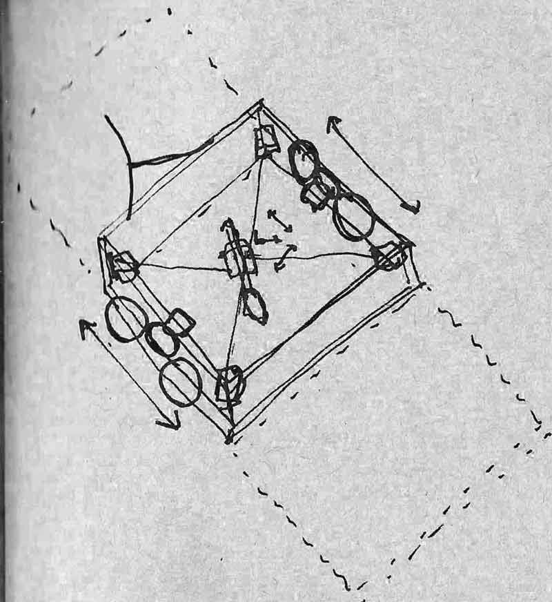
This sketch variation uses a tension wire system articulated with four motors for four cables, two for wheel motion, and one for the brush effector. I am now thinking there may be a delta, three motor, variation on this depending on the wheel configuration not interfering with the drawing surface.
I hope to develop a machine that can stand amongst the following calligraphy inspired machine projects. Wonderful work by Nicolas Hanna.
Junjiao Gan and Xu Zhang sing a Kuka arm.
Training a robot using a motion copy system.
Cable driven system.
Professor Xu Yangshang's calligraphy arm.
I will post links to resources I have found helpful here.
- Timeline of Computer History : Snapshots of the story. 1967, Seymour Papert designs LOGO, Star Trek debuts with multiple computation.
- Brief History of the LOGO turtle : Beginnin gin 1948 with Elmer and Elsie...
- Low-Cost, Arduino-Compatible Drawing Robot : Instructable for a drawing robot.
- Dood : 2014 Fab Academy student, Matthieu, builds a drawing robot as his final project.
- Ideal qualities in a drawing robot pen holder : Great research post on the MakerBlock blog.
- Microbot : Building instructions for the v2 Miro(draw)bot kit.
- Der Krizler : Detailed post about a tension based wall drawing bot.
Share this post...
« Previous post :: Breathing light : An arduino experiment
I now have a grasp of making slight adjustments to code and uploading code to my board. Now that I have a little taste, I want more, so I imagined a simple idea to go a step beyond the tutorials and example codes. An interesting thing to me about coding is how the process is not linear, like what can often happen in other design fields. I can start layering in code and then make a little game of optimizing that code for editing, total number of executions, or number of lines, for instance. In fact, speaking of games, I...
Next post :: Fabricating a gestalt stage »
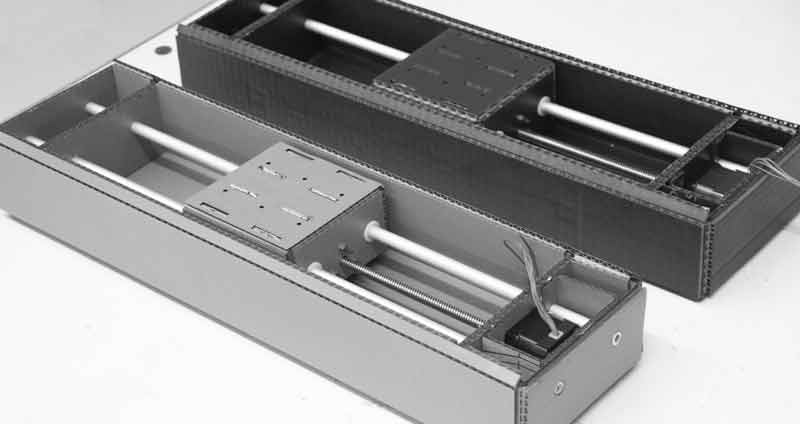
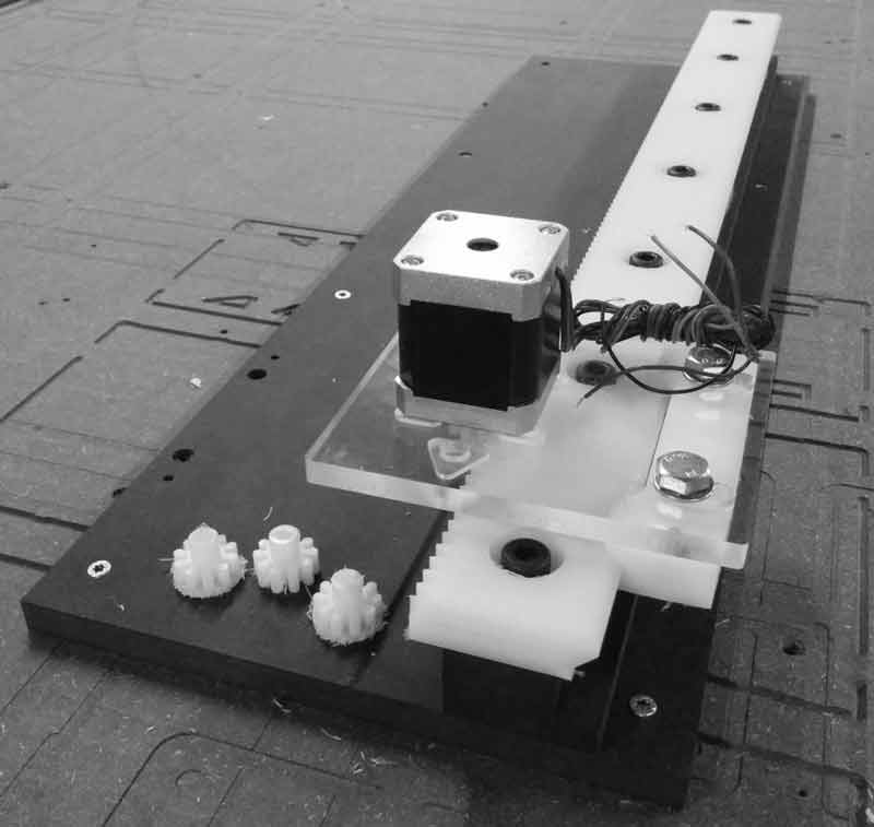
After much intense strategic consternation, we decided to begin our project by developing through the Gestalt framework. The framework is developed; we are beginners. Can we connect rotary stages on either side of a linear stage equipped with a brush effector? The idea is similar to a common CNC machine. Wheels mobilize the whole assembly along an infinite X axis. A stage holding an effector moves a limited distance between two wheels (Y). The effector moves a minimal distance along the Z axis. The first step is to fabricate a linear stage. Download the Rhinoceros file and you may need...