2017 Apr 23
#model3d
#cut2d
#print3d
#dishuBot
#machine
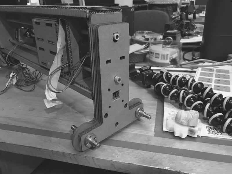
Now we have an operational prototype. Now we have a barely operational prototype. We decided I would focus on the mechanics of the second prototype. I wanted to improve several aspects of the first prototype. One, the robot should be easily portable, which I think works best if it can be easily dissambled and assembled. Two, the wheels do not balance the robot. Three, the effector and stage should be customized to the dimensions and requirements of this robot.
In this section I will focus on the wheels, or the (Y) axis, the infinity axis. First, Saverio found this video which inspired the design.
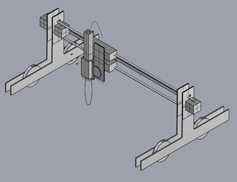
I thought it would be interesting if the metal rods were freed from the cardboard frame, enabling them to be any length, perhaps even variable depending on circumstance. Instead of using a screw to drive motion on that axis (X), we could use a toothed belt, which may easily be adjusted for length. The wheels needed to be detached from the motor and repositioned for balance. I thought we could use two pieces of material sandwiching the wheels and a belt to translate motor movement to the wheels. The belt would also protect the wheels from wear and give greater friction. Finally the stage needed an element to grip and tighten the open end of the belt and an effector for the brush. The brushes we have are large enough to run a tube down the center of the stem, so maybe it makes sense to increase the diameter of the verticle guide. For future flexibility, this entire effector armature may be detached from the stage and replaced with either an improved version of itself, or something with a different use. With this in mind, I made this freeform sketch in Rhinoceros. Completely out-of-scale and interrelationships, but it proved to be a helpful reference through the next few steps of fabrication.
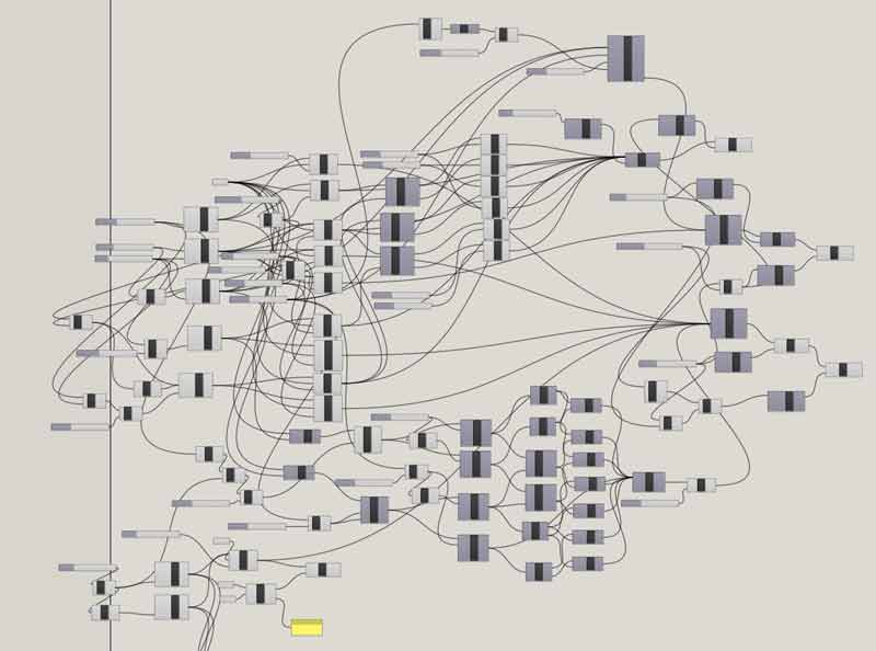
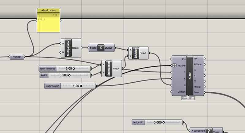
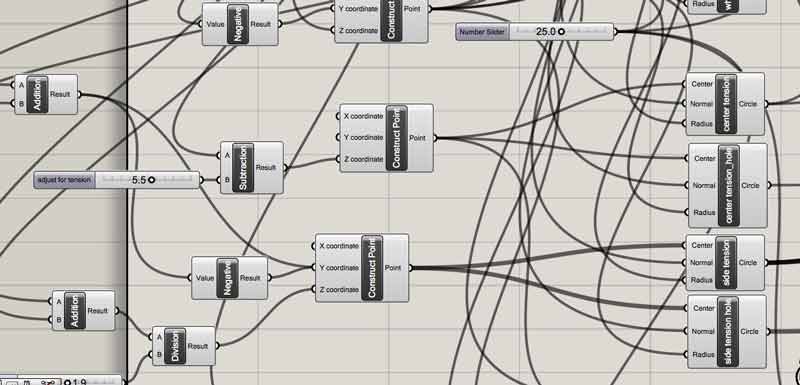
So how about more Grasshopper practice? I can make one hell of a mess in this grasshopper graph. In the future, I will have to explore best practices in keeping the grasshopper graph organized. Fortunately, I can read it and this script made tweaking the wheel armature through prototyping significantly easier. I started with two wheels, the motor with a pulley attached to its shaft, and a single bearing between the wheels. After thinking ahead a little to positioning the motor for the X axis, I decided to move the wheel motor below the rods. When doing so, we were concerned for the tightness of the belt to the motor's gear so I added two more bearings between the wheels and motor.
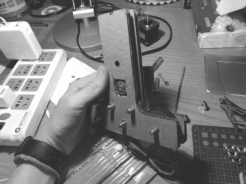
Over to the lasercutter and minutes later I had a working version in cardboard.
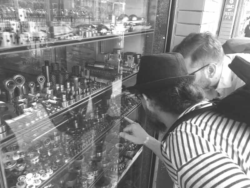
Unfortunately, we did not have bearings or closed toothed belts in stock. To the streets of Shanghai where dreams can be bought on the cheap.
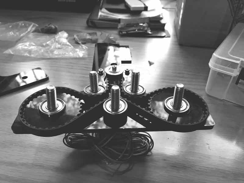
With a fresh batch of parts, I returned to the lab and the cardboard prototype and put everything together. I love it when this happens.
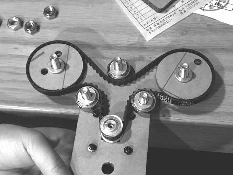
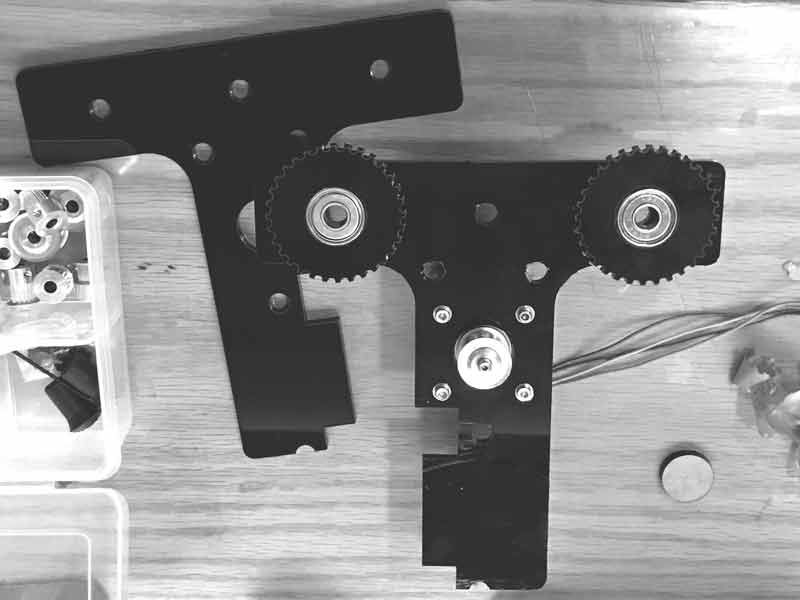
Now I need teeth in the wheels to better catch the belt. I found this grasshopper gear maker referenced in Moritz Begle's FAB aacademy page. What better point of reference than a FAB academy page? Use a gear maker in grasshopper to cut wheels. There are many tools included in that package. I only needed the gear tool. I used a little maths to find the circumference of the circle for the number of teeth on the gear. My purchased belt had a 5mm pitch. I had to cut a couple test wheels to calibrate for laser kerf.
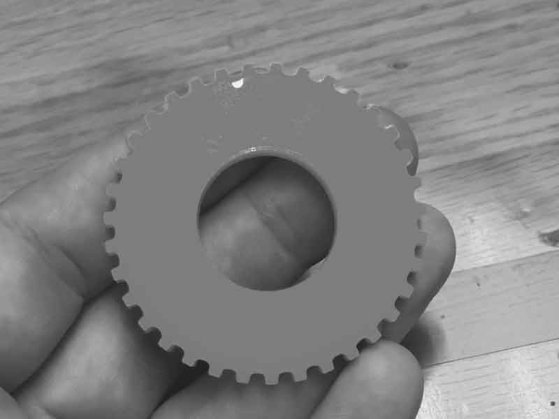
With properly coordinated gear wheels, I returned to my cardboard armature and tested. Brilliant.
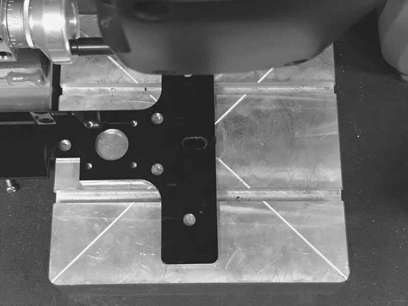
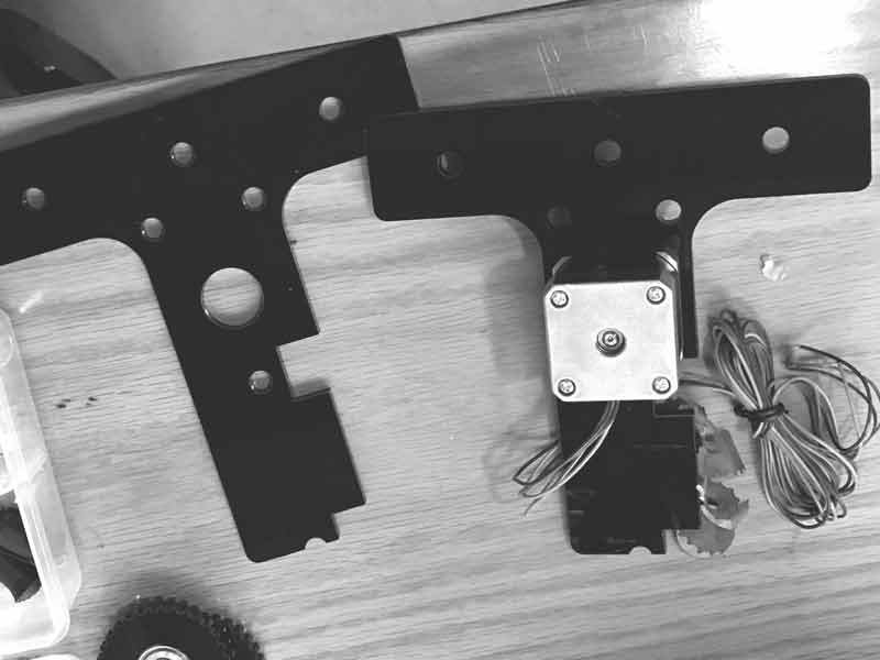
Finally, I wanted to use stiffer material than cardboard for this armature, so I went to the acrylic stock I was using for the wheels. The material is far less forgiving than cardboard, so I needed to adjust the bottom middle bearing location to relieve belt tension. I did this first on the drill press and then translated my findings into grasshopper and back out to the lasercutter.
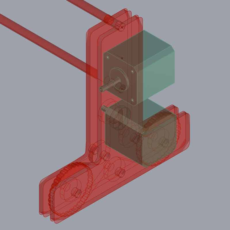
There are some [mechanically] viable wheel armatures. By this point I had already begun sketching a piece to hold the rods and motor for the perpindicular axis which I will document in the following section of the page. The joints cut into the top of the wheel armature were made to slot into this next piece. Because I was working quickly, I made some decisions and followed through on that next piece. I decided this armature will slot in and the rod will help pin it in place for extra structure. And I added holes facing the motor screws on the opposite wall so I could unscrew or tighten without dismantling the entire armature.
A few final notes on this build. The lasercutter makes a mess on the bottom side of the acrylic. So I oriented my cut files so the messy side would be the inside side of the armature. Also, there seems to be a balance of when to remove the acrylic from the stock after cutting. Too fast, and it is horrific smelling. Too slow and it seems to lightly bond back together.
I will post links to resources I have found helpful here.
- Evolvent & Gears : Grasshopper gear script I used.
- Grasshopper gear script : Another gear script I tried but did not like as much. This is better in that it is clear what is going into making the gear.
- Grasshopper Gear simulator : I thought this would be interesting to try but never had time throughout this build.
- How to read a screw thread callout : Because sometimes we are doe-eyed beginners.
- Generic Step Motor Datasheet : The basic dimensions of these motors are all very similar, and my specific steppers I had a hell of a time finding datasheets, so I used this to build a virtual reference model.
- CNC Tank : Youtube design that inspired the wheel design.
Share this post...
« Previous post :: Prototyping a belt axis
The Gestalt linear stage used a screw drive mechanic which we thought would be too limiting dimensionally for our purposes. Therefore, we decided to change this axis to a belt drive mechanic. I also wanted to see if this axis could be freed from the cardboard structure of the Gestalt model so it might have interchangeable rod lengths. I went about designing these pieces thinking three-d printing would be the optimal method because I could make non-planar things without worrying about connections and alignments. Three-d printing is slow. Three-d printing, however, is also passive which lets me focus on other...
Next post :: Bioelectrochemical testing pod »
I would like to begin prototyping grow modules for Pure Imagination. The first challenge is setting up a plant microbial fuel cell system for generating electricity with moss. This work will heavily rely on the scientific research from Paolo Bombelli, et al. I thought I could cast this pot... ...and thinking how to do that with ooloo is tough. I think slip casting or vacuum forming would be the easiest route. I have experience vacuum forming and more, and would have some concern with the finishing that would need to be done after pulling a form for this object. If...