2017 Apr 23
#model3d
#print3d
#dishuBot
#machine
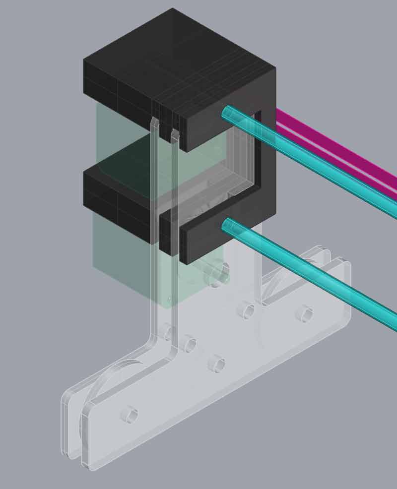
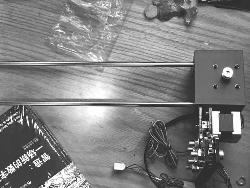
The Gestalt linear stage used a screw drive mechanic which we thought would be too limiting dimensionally for our purposes. Therefore, we decided to change this axis to a belt drive mechanic. I also wanted to see if this axis could be freed from the cardboard structure of the Gestalt model so it might have interchangeable rod lengths.
I went about designing these pieces thinking three-d printing would be the optimal method because I could make non-planar things without worrying about connections and alignments. Three-d printing is slow. Three-d printing, however, is also passive which lets me focus on other things while the machines are working (designing the wheel armature and effector). These sections are not organized based on time.
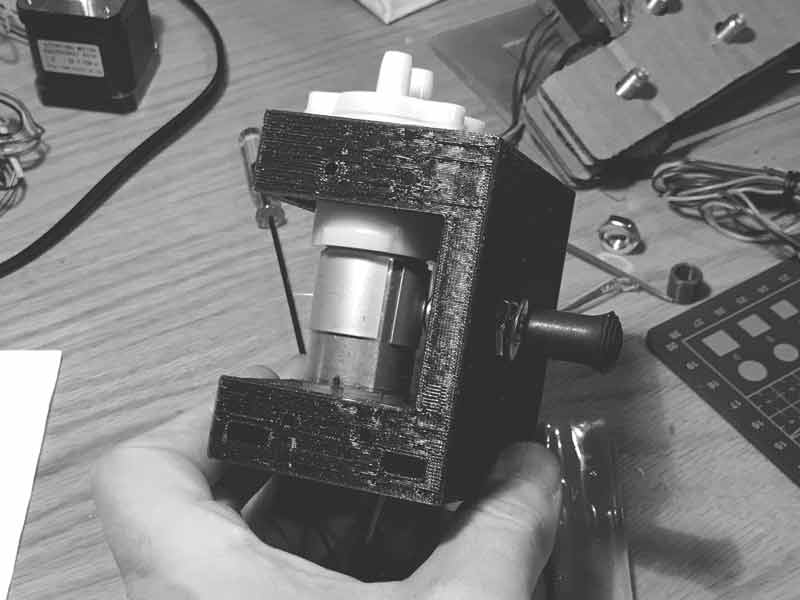
My design was a modification of the gestalt stage, stripping away unnecessary parts and slotting connections for my wheel armature, stepper to drive the (x) axis and DC water pump. That in mind, the design of the first piece was straightforward.
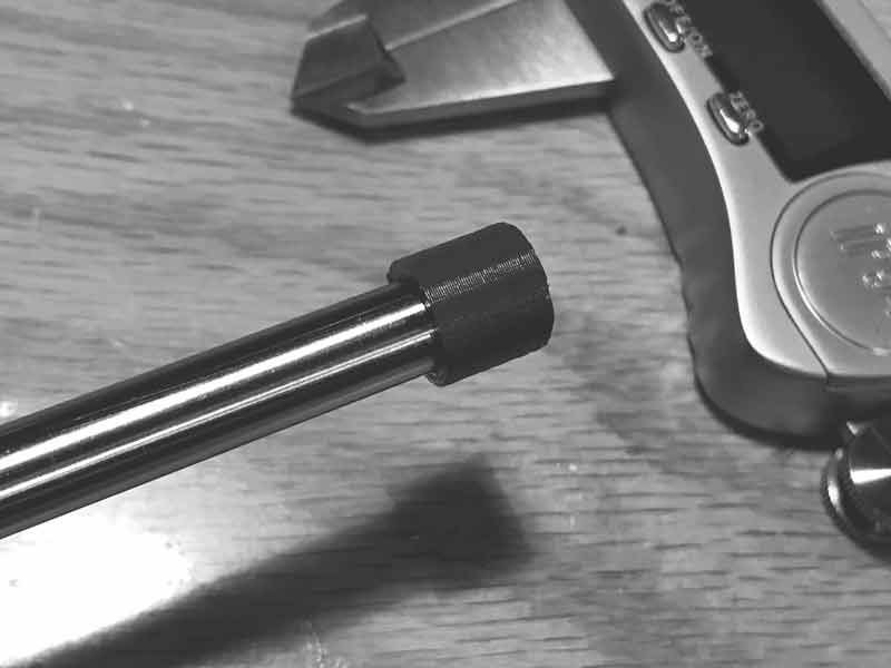
Keep in mind, 3d printing can sometimes take hours to produce a single piece. You better test critical parts of the print first. By testing the rod fit, I found the printer was adding 0.4mm of material with my settings. Rather than try to properly calibrate my settings to the printer, I decided to adjust my 3D model. This is an easier thing for me to control.
Then I printed the first piece. I printed this piece with Makerbot tough PLA and a 0.2mm layer height, 3 layers on the external surfaces and 20% infill. Along with the overall wall thicknesses, the layer height was overkill and made this an 8 hour print when it easily could have been far less. In fact, with future pieces, I used 0.3mm layer height and the prints of similar size were finished in under four hours.
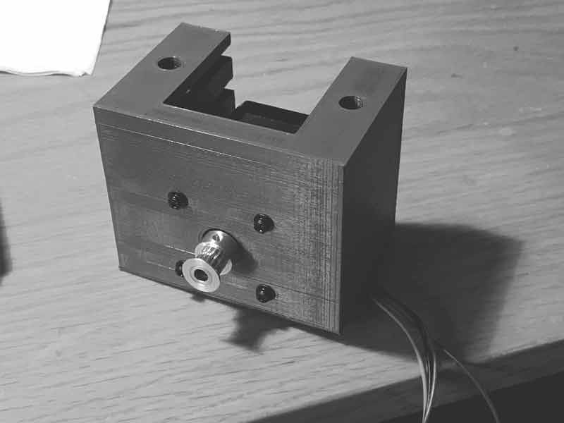
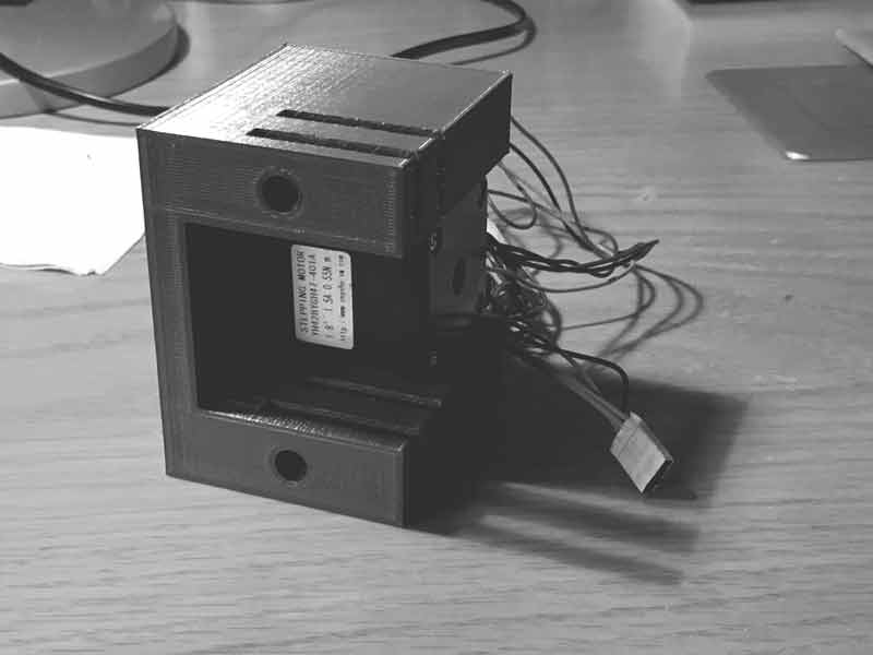
I made an assumption about how much space I would need for the wheels inside the two layers of acrylic before I purchased materials. Happily, I was correct. These photos were taken before I resolved the wheel belt tensioning issue.
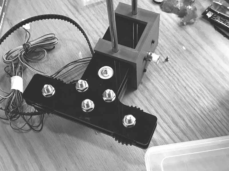
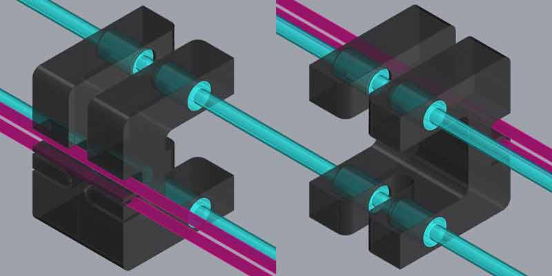
On the other side I made an M8 sized hole for a TBD belt bearing and made space for the water pump and wires. I also added expansion slots for a water shelf and zip ties.
I printed this with the Smart Extruder+ and normal PLA at 0.3mm layer height. Much quicker and no noticeable structural negative.
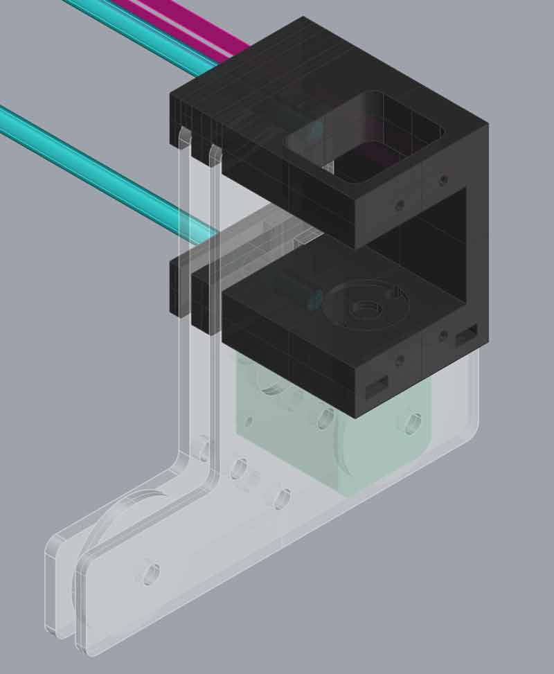
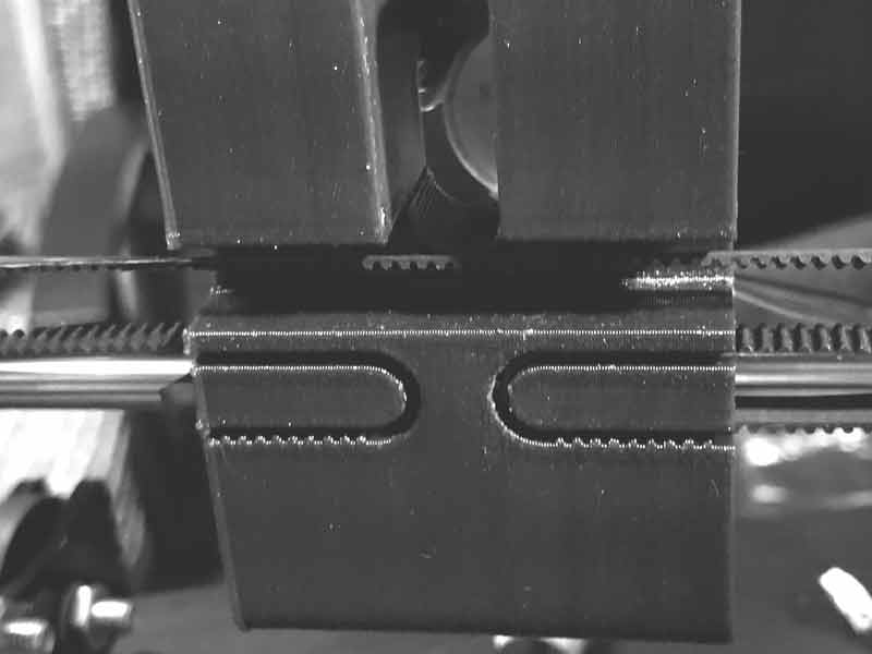
Finally for the stage, I started to think about ways to carve away unnecessary material and give the robot some style. I used a U-shaped channel to tighten the belt and deal with the slack. It works but it is tricky to push the belt into place with tension. I think on another try I may make it something like S-shaped, so I can tighten the belt, hold it in place and then put it into a teethed section. Or, how about this? I might look for great ideas already in use.
I test printed the belt and rod bearing fits. Initially I had teeth going all the way around the belt fitting. It was overkill. Glad I tested first.
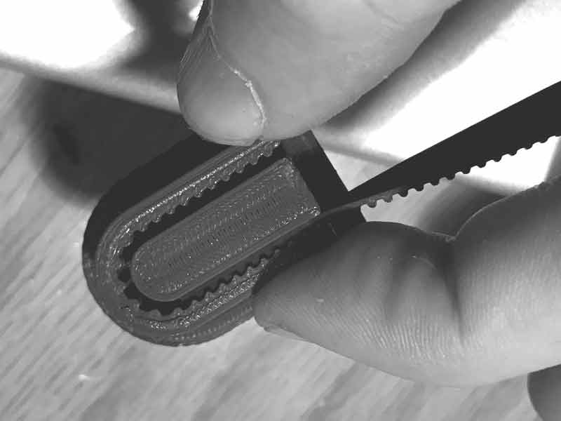
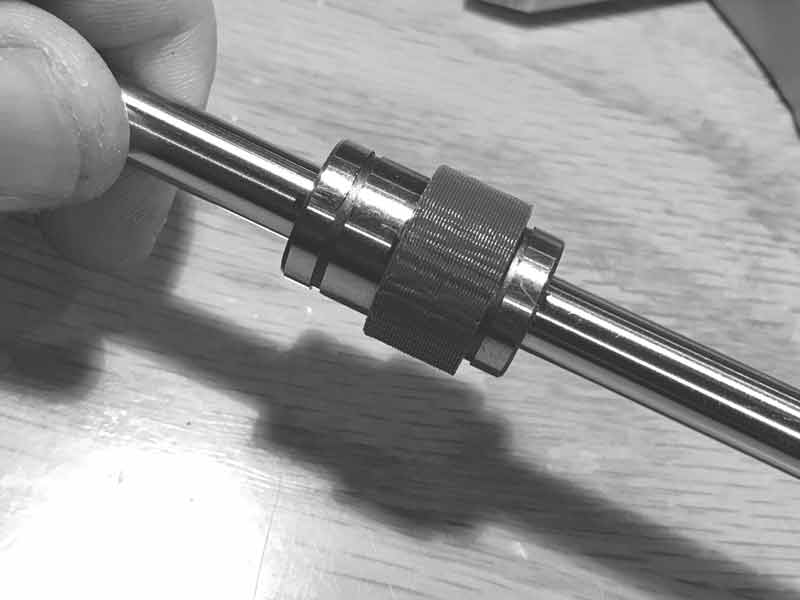
And the final fit of the belt tensioner.
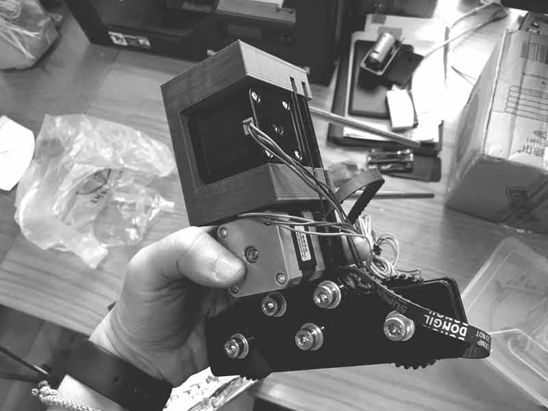
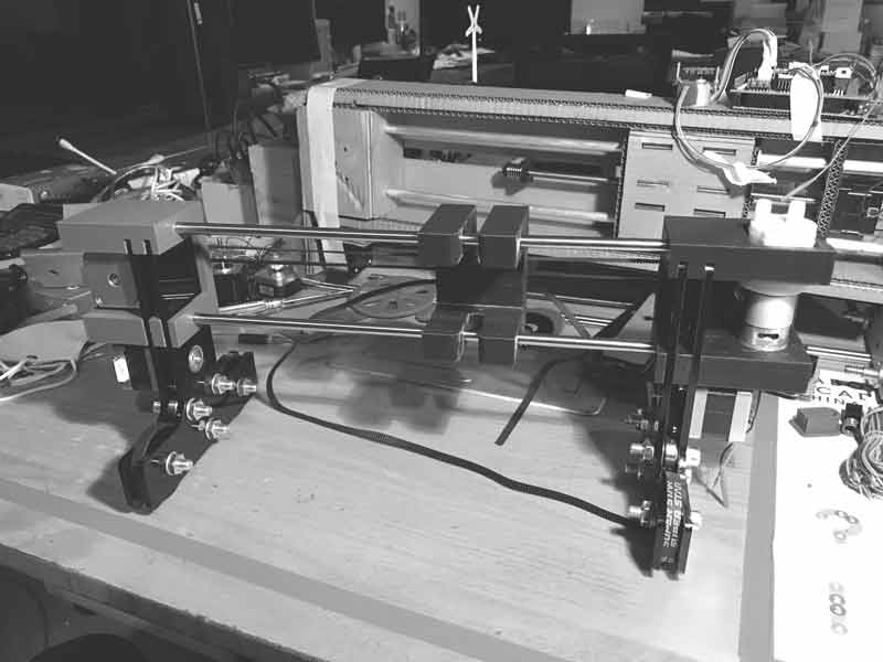
The robot is coming together.
I will post links to resources I have found helpful here.
- 4xiDraw drawing machine : A machine I checked out while making.
- 28BYJ-48 Step Motor Axis : A machine I checked out while making.
Share this post...
« Previous post :: Prototyping the effector
The effector pushes the brush into the drawing surface and pulls it away. Included in the mechanism is the flow of water from the reservoir into the brush tip. This design uses a 2BBYJ-48 stepper motor we had in stock in the lab. Precision of movement is not needed. In the design of the stage, I left some gaps that could be used to attach an effector shield. We also looked at an effector designed by Simone Boasso previously. With these starting points, I designed this: I created a larger guide for the vertical movement with a perpindicular axis for...
Next post :: Prototyping the infinity axis »
Now we have an operational prototype. Now we have a barely operational prototype. We decided I would focus on the mechanics of the second prototype. I wanted to improve several aspects of the first prototype. One, the robot should be easily portable, which I think works best if it can be easily dissambled and assembled. Two, the wheels do not balance the robot. Three, the effector and stage should be customized to the dimensions and requirements of this robot. In this section I will focus on the wheels, or the (Y) axis, the infinity axis. First, Saverio found this video...