2017 May 17
#coding
#electronics
#dishuBot
#machine
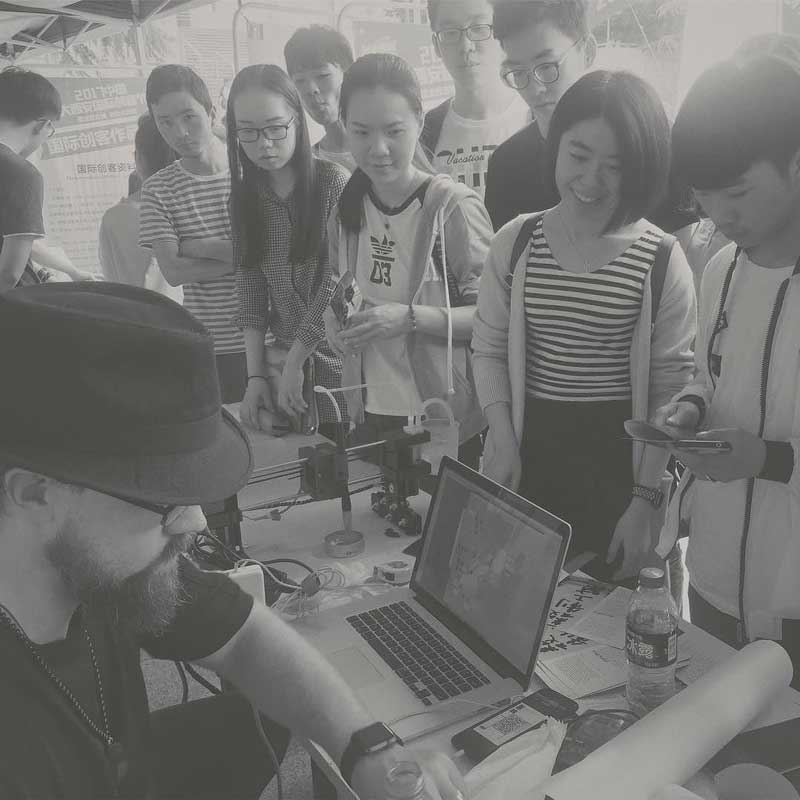
When writing Chinese characters, there are rules. You can either abide or you will be revealed a fraud. When we first tested the machine, we tried several online g-code generators (link?). One thing we did not find was a good way to specify stroke ordering and directionality. I was excited to show some Chinese people the first successful tests of our machine and everyone criticized the machine's stroke order!
I started to investigate the possibility to write code we could use to generate g-code which follows the basic principals for patterning strokes in Chinese characters. And, this was a good excuse, as the thought of being able to control g-code throughput has intrigued me since three-d printing a couple months ago. Throughout the past couple months, I have had fun learning the Grasshopper plugin to Rhinoceros so I decided to start with Jens Dyvik's Bark Beetle - parametric toolpath plugin for Grasshopper. Unfortunately, there is a plugin compatibility issue I could not solve with Firefly on MacOS and the graph was out of my comprehension level. I will return to it soon.
Searching around I found two fantastic webposts. This instructable: Make Awesome 3D Geometry by Programming CNC-code by Siemenc and G-Code Writer for 2D Shape Milling. The latter was mostly outdated through Grasshopper updates but the concepts Andy Payne (same person behind Firefly) discusses in the video are still relevant; I ultimately built systems based on these concepts. I started with Siemenc's open-source grasshopper code for controlling shopbots, only slightly outdated, and adapted it to our purposes. By this time, the original grasshopper code is nearly unrecognizable.
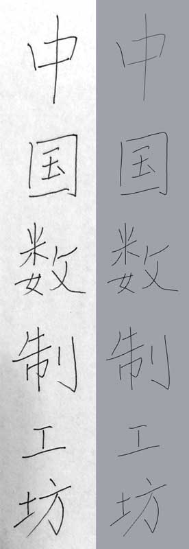
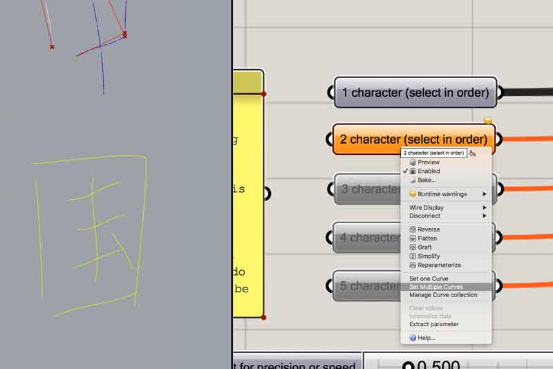
First, you need to develop single line strokes of the characters. We have used Inkscape and Illustrator tools for generating vectors from rasters, written into the computer using a mouse, and creating single line vectors from typefaces. All are imperfect methods and I hope to find a better way. Handwriting on the left and rhinoceros single line version on the right.
Each character, which is a set of strokes in succession, is inputed into a single module grasshopper curve module. Right click on the module and choose: “Set Multiple Curves” then in Rhinoceros window, choose each set of strokes in succession from first to last. The ordering can be double checked in the preview cluster.
If you are not using all the characters, turn off the extra modules. If you want more, duplicate and connect the output to clean module. Hold down shift when you do this, or it will replace all the previous connections. The character modules must be connected to clean module in order first to last.
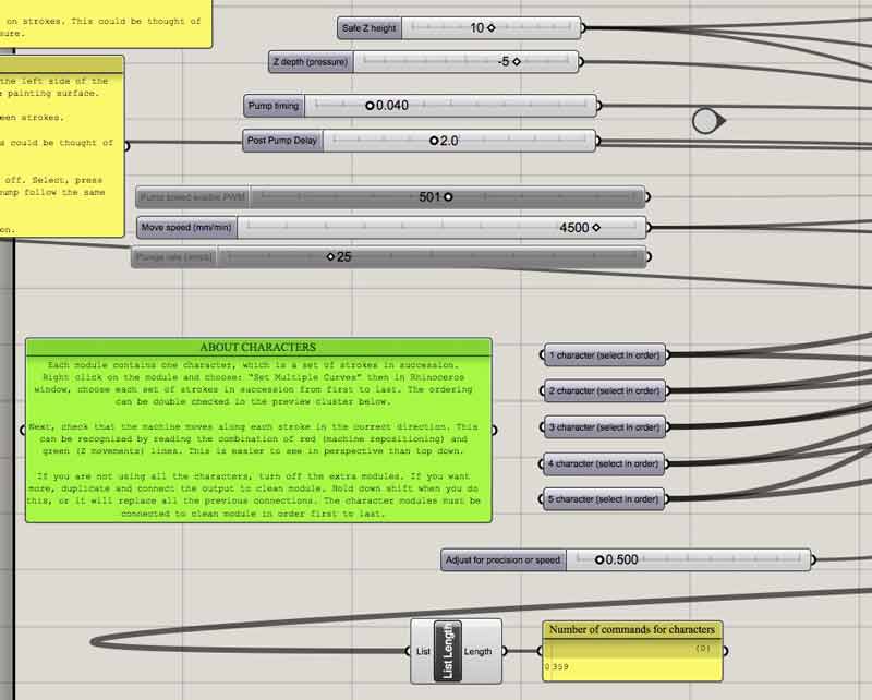
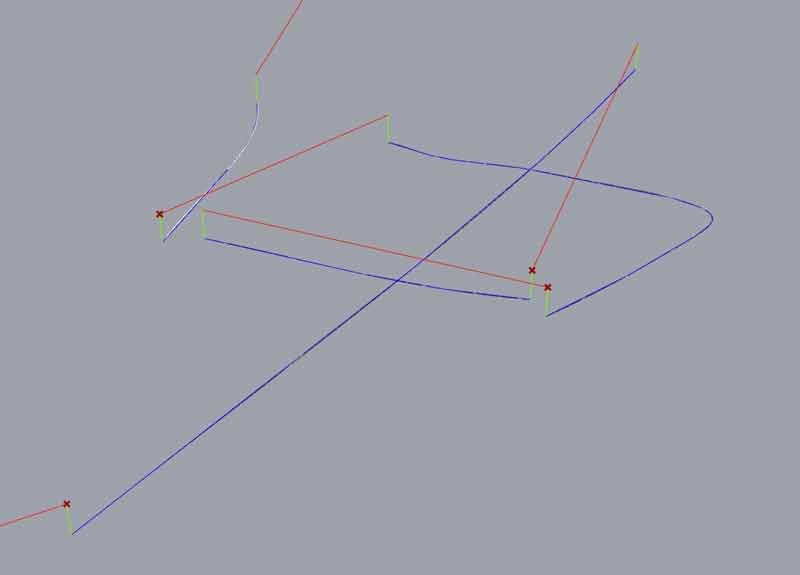
Next, check that the machine moves along each stroke in the correct direction. This can be recognized by reading the combination of red (machine repositioning) and green (Z movements) lines. This is easier to see in perspective than top down.
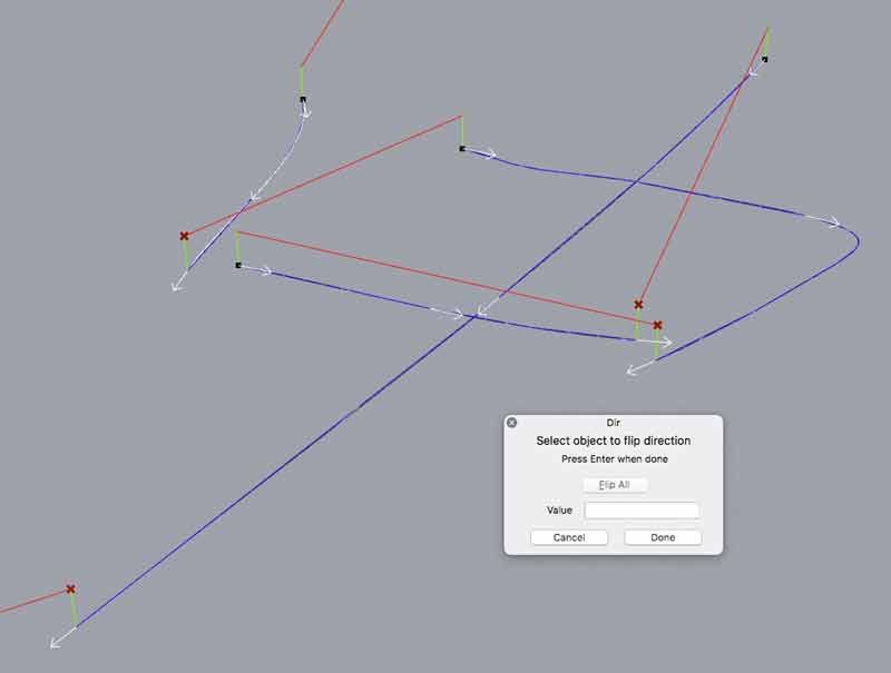
If your robot is painting in the wrong direction, it can be changed with the "flip" or "dir" command in rhinoceros. "Dir" shows helpful arrows.
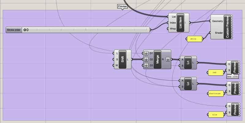
Change this slider to review stroke sequence. If strokes in a character are out of sequence, correct the order of the list in the corresponding character module, for instance, reselect. Bear in mind 0 is first.
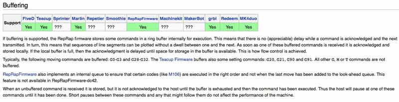
Nobody in the world wants to wait on a slow machine. For your speed needs, dishuBot can book it, assuming you understand its limitations. First, tune the stepper drivers and ensure the mechanical operation is excellent, this is discussed in another section. Using GRBL and the CNC Shield, the most important thing to understand is serial communication delay. GRBL queues around 10 commands. If the machine exhausts the queue of commands faster than the serial communication, it will stutter while it awaits serial transmission. This is from the RepRap Wiki:
A precision setting adjusts the segmentation of the curves as all the G-code is parsed in segments currently. The lower the precision setting, the more segmented the polylines that make up the curves will be. Each point along the polyline will be converted to a machine coordinate. More points, more coordinates, longer code. However, list length is a placeholder reference that does not mean much really. It is just there for feel. The real thing to do might be to calculate the length of every set of queued commands, predict how swiftly the machine will draw and factor the serial delay. Then the precision adjustment may not be necessary as the code will automatically adjust precision to serial transmission rate vis a vis movement speed.
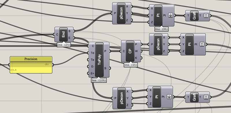
Maximum movement speed is calibrated within the Arduino code or GRBL. I set the maximum to 5000 mm/min. I am sure it can move faster so I intend to return to this setting in the future. Commands following a “G0” prompt will move the machine at the maximum speed automatically. Commands following G1 are painting strokes. These commands are dictated by the move speed slider. G0 are jogging movements. Near the top of the G-code, I have G94, which sets the machine to a units per minute feed rate and G21 for millimeters.
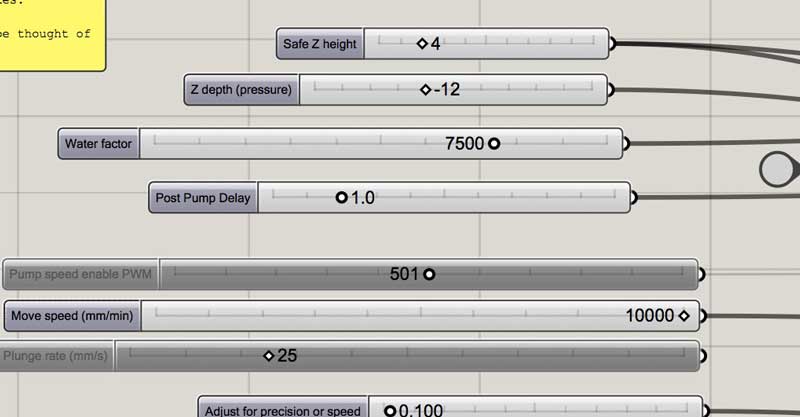
Before using any G-code with dishuBot, move the stage near to the left side of the wheel axis and set the tip of the effector medium just to the painting surface. Safe Z height is the height the effector moves up between strokes. Z depth is the distance the effector moves down on strokes. This could be thought of as stroke pressure.
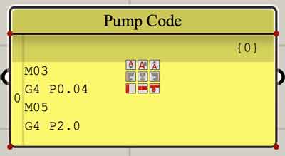
Pump timing sets the amount of time the pump turns before stopping. M03 is relay low (pump on). G4 is delay and P(number) is timing. M05 is relay high (pump off). Calibrate this to your surface material and effector medium. Post pump delay is an optional machine delay to permit the effector medium to saturate. During this time, the machine will do nothing before resuming painting. Both settings are in seconds. If not using the pump, switch the Pump Code panel to the left off. Select, press space bar once, select “Disable”. If you want to renable the pump follow the same procedure and press “Enable”.
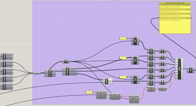
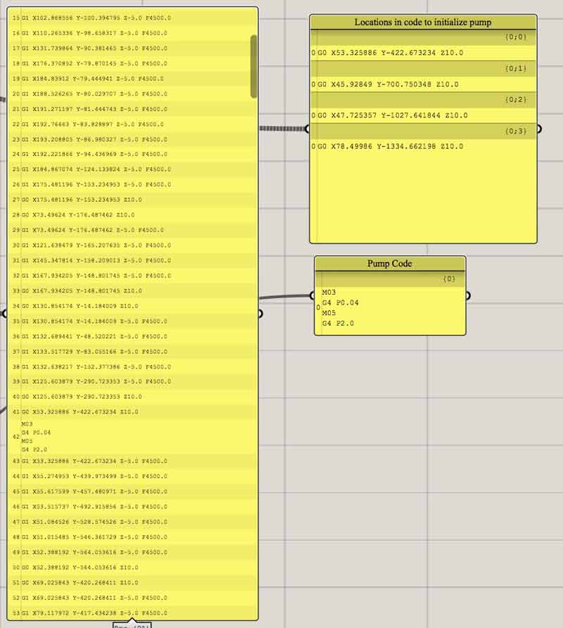
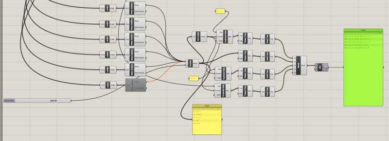
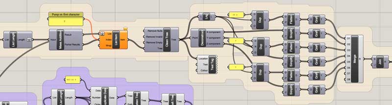
These are the points in the code the pump is activated. Currently, the pump is not active on the first stroke, assuming the brush is saturated before beginning the job. If you would like to activate the pump on the first character, add a connection between the top First Value and Curve holding shift. Disconnect it to deactivate.
This code searches the G-code for the starting points of each character and inserts the four lines of pump control code there.
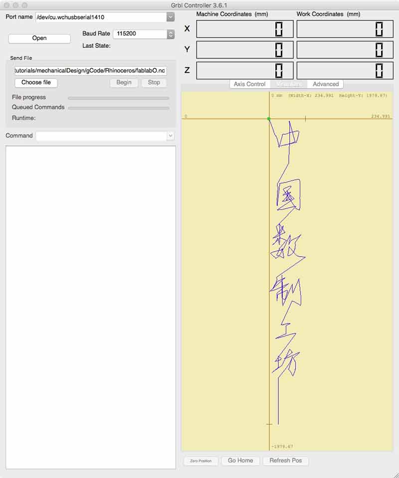
Finally, there is a panel on the right side of the graph with all the G-code. Right click on this panel and setup a stream destination with the *.nc format and enable stream contents. Now a file will be automatically updated as modifications are made in the grasshopper graph.
And the file can next be loaded into GRBL for painting.
Update: I found two mobile apps that work well for touch screen drawing vectors, ie Chinese calligraphy, that can be used in the Grasshopper graph.
With either of these apps, you can transfer drawings from your fingertips to dishuBot in just a couple of steps. This eliminates the tricky process of converting image scans, or typefaces to single line strokes for the G-code script. Both apps require in-app purchases to export vector files. CREATE can export PDF via email. Vector Touch can export SVG and PDF via email. Rhinoceros can read most PDF files. I will break down my use of each app.
CREATE exports PDFs which can be directly exported to Rhinoceros. In my tests, Grasshopper remembers stroke order and direction. I recommend you double check this each time regardless. Follow the steps in the GIF below. Open the app, press the plus button, choose the curvy line, remove the fill, draw, then press the square with the angle button, choose vectors and email the file to yourself. This application does not have good options for changing the artboard beyond the screen size. Sometimes the CREATE does not properly export the vectors, when this happens, I return to the application and export again or draw another shape on the screen then export. I have yet to isolate a pattern in the error.

Vector Touch exports PDFs which Rhinoceros does not like. You will need to open these in another application, ie Illustrator, and save the file. Then Rhinoceros will have no problem. Vector Tough can also export SVG. However, Rhinoceros does not have the capability to import this type. Open the file in another program, ie Inkscape, and save in an acceptable format for Rhinoceros (many). Vector Touch, in my testing, is also capable of exporting the vectors into Grasshopper in sequence and direction. You can set a canvas size in the app and import the drawing to scale in Rhinoceros. And, this app supports standard iOS Pan and Zoom gestures. Choose the plus sign to make a new drawing, or just use a custom canvas already in place. Then choose the canvas dimensions in mm. The maximum Y direction is 722.4mm but if you set the X dimension to some factor of the machine's dimensions, it will scale the canvas. Choose the freeform curve draw tool, set the fill to none, draw characters. Pinch and two finger pan inputs are present. Press the square with the arrow button and export the file via email.
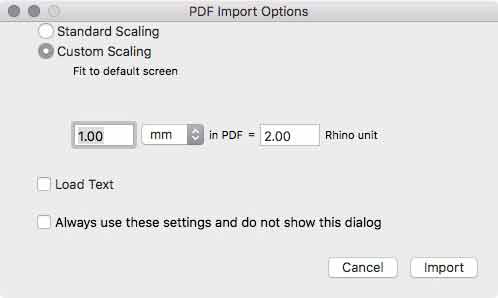
In Rhinoceros, import the vector drawing. Depending on how you tune the import settings, the drawing will likely be out of scale. One quick fix is to select all the curves and use the boundingbox command, which will draw a rectangle fitted to the extents of the group of curves.
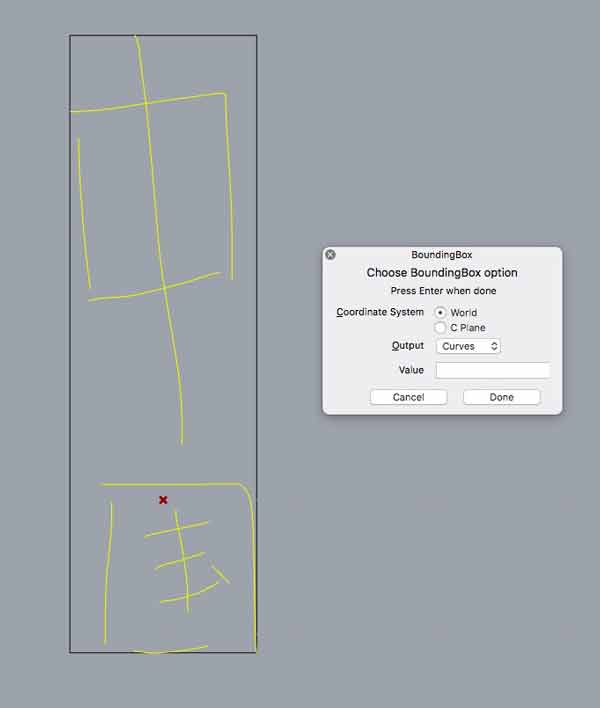
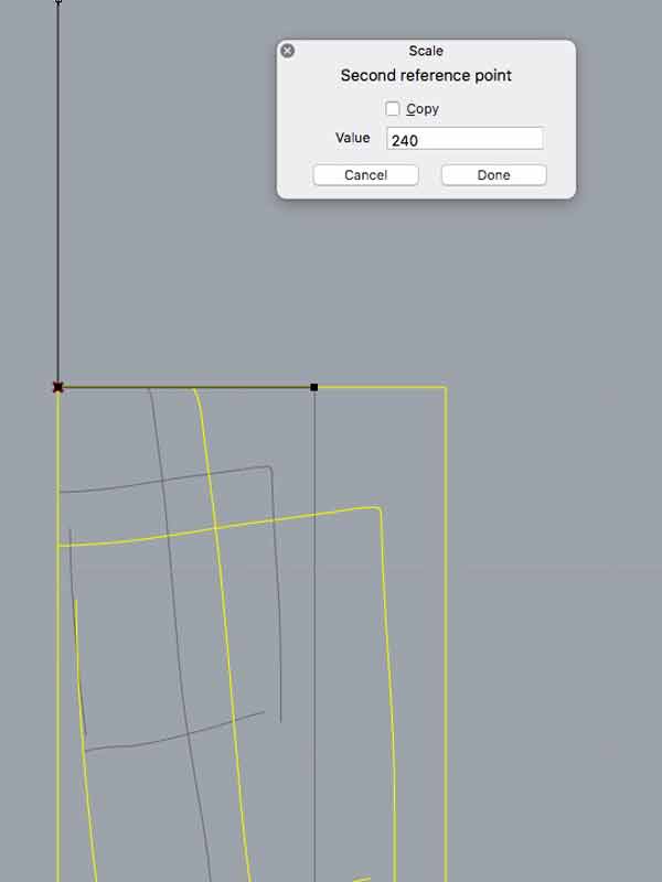
Then use the move command, choose the upper left hand corner and type in 0, press return. This will move the curves to the machinable area. Next use the scale command, choose the upper left corner of the box followed by the upper right corner and type in your desired width. Now the characters are properly scaled for the robot.
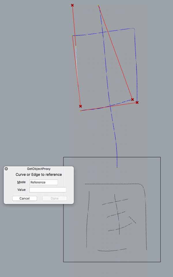
If using VECTOR TOUCH, it is possible to export to scale if you setup the canvas correctly. In my example, I set the X dimension half of the machine working area then fixed the scale on import. The drawing will be imported in the X+, Y+ zone of Rhinoceros working area. Simply move the drawing to the X+, Y- zone. In this case, Y -1444.8mm.
If using CREATE, the vectors seem to come into Rhinoceros in sequence if you follow these steps. Right click on a Character input in Grasshopper. Choose "Set Multiple Curves".
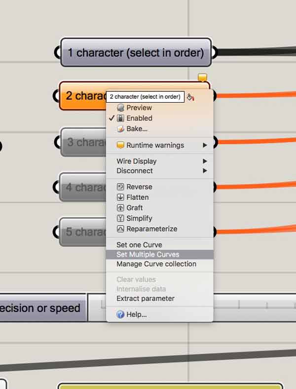
Next, draw a window around the character in Rhinoceros. Good to go. I recommend double checking direction and sequence as described above.
If using VECTOR TOUCH, do the same in reverse. First select the character in Rhinoceros with a bounding box, then choose "Set Multiple Curves" on a character input in Grasshopper.
Update (11 June) : Based on more experience using VECTOR TOUCH with volunteers, it seems to reverse or not the order of the characters, perhaps based on the file format used to prepare the file for Rhinoceros. Either check the stroke order on the first character inputed, or reverse the modules as needed.
As mentioned in the effector section, now in the code, I want a relationship between the length of the character drawn and the pump timing. In this, I use grasshopper to define the pause length between setting the relay to low and high, or the amount of time the pump is activated which correlates to the amount of water pumped. Perhaps in the future, a sensor could be used to make a closed loop system from the brush reservoir level to the amount and timing of water pumped.
M03 G4 P0.072172 M05 G3 P1.0
M03 G4 P0.100443 M05 G3 P1.0
M03 G4 P0.117917 M05 G3 P1.0
M03 G4 P0.108700 M05 G3 P1.0
M03 G4 P0.027820 M05 G3 P1.0
For some time now, I have had trouble understanding how to correctly handle lists in grasshopper. I went to The Grasshopper Primer and read the sections on lists and trees. Upgraded abilities. The new section looks like this. The left side, what was once one component per character is now one for any number of characters.
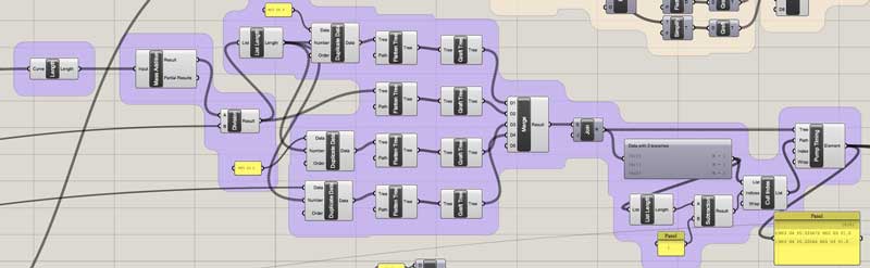
Pump timing was changed to a water factor. Finding the correct factor without a sensor embedded in the effector stem to check water level is by feel based on a couple test runs, the drawing medium, brush pressure and other environmental variables. When calibrated, the water factor variable is a divisor of the total stroke length of the previously drawn character. I have not had a chance to test it on the machine yet, however, the programming is effective in generating the code and inserting the variable pump timing correctly within the movement code.
This chunk of programming finds the insertion points for the pump timing. Again, largely simplified from the previous version based on better understanding data trees and lists. Essentially a list is a set of data that would be considered as a single branch of a tree. Branches (each containing a list) can bifurcate, at the very least many times forming complicated trees.
At this level, I think I will next focus on my efforts to transition to Firefly control the outputs instead of GRBL and start prototyping the "Yong" strokes and character mapping. I recently exhibited the machine at the 2017 Maker Festival in Xi'an and welcomed tremendous feedback, including suggestions to enable twisting and tilting of the brush, movement sensors, which Neil also suggested, encouragement to explore different styles of strokes and wide enthusiasm for the lofty goal to digitize the Chinese character library in strokes.
Currently, I am interested in these next steps of development:
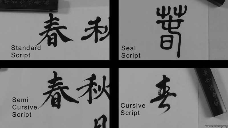
- Push handwritten code to create as beautiful characters as possible. Below are four examples of the world "spring" in different styles.
- Test with wider X axis configuration.
- Program the machine to rotate.
- Connect battery and optimize electrical wiring
- Build modular components for the logic board, water and battery
- Find way to send code without my computer connected with a wire
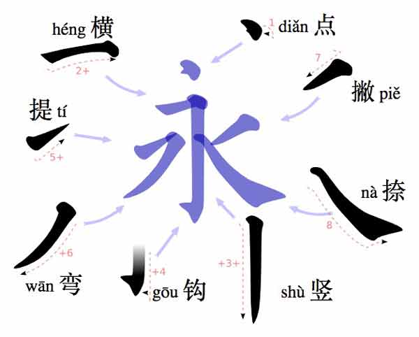
Future intention: There are a limited number of basic strokes which comprise all Chinese characters. Some systems of identification find up to 37 different strokes, while others have distilled it down to just eight. I intend to optimally code brush movement for each of the basic strokes in code modules then map configurations according to desired character output. This Chinese character "Yong" meaning "permanence" is often used to teach the eight basic strokes (because they are all present). With defined rulesets for stroke ordering and knowledge of the strokes (components), code may be able to scan charcters and find the stroke composition automatically. I foresee a problem in that simply using this approach might output characters that are too "machined". Perhaps there is a secondary set of rules that create unique distortions based on stroke proximities, ie water/ ink saturation points, momentum, or even emotional content of what is being written. Another further step could be to use the stroke and character library as a basis for the code to learn stylistic distinctions of people and adapt those across its own stroke modules.
I will post links to resources I have found helpful here.
- G-code Wiki!! - Do not screw around, this is your number one resource for writing g-code.
- Stroke Order for Chinese Characters : Background for Chinese handwriting.
- The Importance of Strokes in Chinese Characters : Background of the eight basic strokes that compose most Chinese characters.
- Relative vs Absolute Coordinates : An explanation of use cases for each in writing g-code.
- Treesloth : Advanced set of tools for managing Grasshopper lists.
- Grasshopper list searching : Index searches require an exact match of all components within an indexed item while Member index searches work simply on values.
- CREATE App : Draw vectors on your iDevice and export to Grasshopper G-code writer
- Vector Touch : Another way to draw vectors on iDevice and export to Grasshopper G-code writer
Share this post...
« Previous post :: Networking light : Twin PCB
I was introduced to a project by Enrico Bassi which uses two ATMega boards connected to IR Sensors and IR LEDs to network by reading pauses in IR light (low). Upon seeing it, I was immediately impressed with the visceral qualities of networking with light. It is visible to our eyes! And, we could control a light in our hands to communicate to a machine. Admittedly, low tech stuff here. Remote controls... Plus, technically, we cannot see the light, the red LED on Bassi's board is for human reference, the IR LED is invisible to us. Regardless, as a first...
Next post :: Testing the electrical components of the IR network twins »
Infrared light is invisible to the human eye, so it is a challenge to know if the infrared LED is operational. Further, the sensors need to be operationally tested. I setup some simple arduino sketches to confirm the board. First, you need to match the ATtiny44 pins to Arduino speak. Look at this graphic and compare it to the schematic. The LED is on ATtiny 12, irLED 11 and irSensor 10. One, two, three. I will add those as integars. Now, many cameras can see infared light. The front camera on newer iPhones is one such camera. const int irPin...