Tags
#coding
#electronics
#pureImagination
#microCode
#comm
Pure Imagination
- Environmental monitoring with online data logging to Thingsv
- Inventory
- Hessian/ burlap/ crocus composites
- CNC milled wood frame
- Grow monitors | What watches the watchers?
- Grow module | Design and fabrication
- Grow Module | The science
- Processing Light Graph
- Milling a composite mold
- Composites : Modular growth, testing
- Bio-electro-chemistry
- Bioelectrochemical testing pod
- LCD x Arduino
- Precedents
- Discussion
- Design, Materials and Methods
- History : Early concepts
2018 Mar 31
#coding
#electronics
#pureImagination
#microCode
#comm
Over the past few months, I have continued to develop the electronics and programming aspects of this project. I now have a system for evualating power potential and environmental sensing, and logging all that data online to Things Speak, an open Internet of Things Platform. Previous to using Things Speak, I was logging data to an SD card. However, with an SD card, I need to periodically pull the data from the card. Extra work. Using Things Speak, the data is available to me and everyone else instantly, everywhere. There have been some issues with wifi stability and internet connectivity to resolve; there will be more on that and much more deeper in this post.
TL;DR
- Using an ESP8266-01 WiFi board with Arduino
- Generally wiring an [ LM1117 ] adjustable voltage regulator and specific to 3.3 volt ouput
- Setting up the D3231 Real Time Clock module and how to use it to manage Arduino sleep cycles
- Working with DHT-11 Temp / Humidity and CJMCU-6070 UV sensors
- Furthering power savings with an [ PN222A ] transistor
- Logging sensor data online with Things Speak
Might as well start the documentation with the wifi module. I used an ESP8266-01. This 3.3 volt board does have a pair of IO ports and can be programmed with a variety of different languages directly making it a wonderful tiny IoT PCB. However, I chose to use it to extend an Arduino Pro Mini. There are loads of great guides to setting up the ESP8266 online, so no need to belabor it here. Here is my favorite.
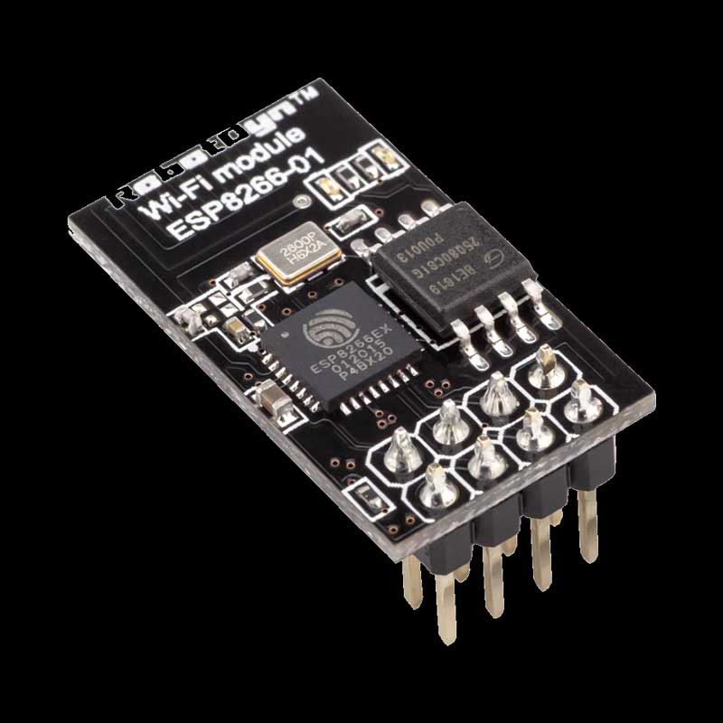
The pinout of the ESP8266-01 is as follows. GPIO0 and 2 will not be used in this project.

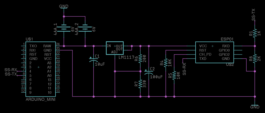
The ESP8266 chip is rated at 3.3V. While it can except slightly higher voltages, the typical 5V arduino output is no bueno. Further, in my observation, the chip can pull up to 300 milliAmps with typical operation between 200 - 250 mA. This is more current than 3.3 V pin on some Arduino boards outputs. With that in mind, I chose to use an LM1117 800mA low-dropout linear voltage regulator I had on hand. I used the adjustable variety.
To output 3.3 volts on any input voltage up to 20 volts, I used a 330Ω for R2 and 200Ω for R1.

To send data back and forth to the ESP8266, you will need to use serial comms. 3.3 volts is enough to pull an arduino input high, however, sending a 5 volt signal from Arduino will eventually burn out the ESP8266. I used a simple voltage divider to step the signal voltage down to 3.3 volts. This is the circuit.

And this is the formula. To step 5V down to 3.3V : R1 is 1000Ω and R2 is 2000Ω.

I am powering this project with batteries. Due to the current draw of the ESP8266, I chose to use two sets of 4 AA batteries in parallel because, that is what I could access quickly. That amounts to about 6V and 400mA. Finally, the CH_PD and RESET pins on the ESP8266 should be pulled up for normal operation. For this, I used two 10KΩ resistors. Pulling it all together, my circuit to connect an Arduino [ Pro Mini ] with an ESP8266-01 looks like this.
The final step with this part of the project is to get the ESP8266 and Arduino to start playing nice. Use this code to test it is working. The ESP8266 is often defaulted to 115,200 BAUD which is too fast for Arduino software serial. So, the first time running the board, you may need to set to 9600 BAUD (works best) by sending the command "AT+UART_DEF=9600,8,1,0,0" or other means, ie. connecting the ESP8266 directly to your computer.
//Libraries------------------------------------------------------------------------------------------
#include "SoftwareSerial.h"

// arduino RX pin,  arduino TX pin
//RX pin to esp8266 module TX pin
//TX pin to esp8266 module RX pin
SoftwareSerial espSerial(4, 5);

String network = "yourNetwork";
String password = "password";

void showResponse(int waitTime);

//SETUP----------------------------------------------------------------------SETUP
void setup()
{
  Serial.begin(9600);

  //uncomment these lines to reset the module to 9600 baud rate permanently
  /*
  espSerial.begin(115200);
  espSerial.println("AT+RST");         // Enable this line to reset the module;
  showResponse(1000);
  espSerial.println("AT+UART_DEF=9600,8,1,0,0");    // Enable this line to set espSerial serial speed to 9600 bps
  showResponse(1000);
  Serial.println("espSerial baud switch");
  */

  espSerial.begin(9600);    //change the arduino software serial baud rate to something it can understand <= 57600
  espSerial.println("AT+CWMODE=1");   // set esp8266 as client
  showResponse(1000);
  espSerial.println("AT+CWJAP=\""+network+"\",\""+password+"\"");  // set your home router SSID and password
  showResponse(5000);

  Serial.println("Setup completed");

  digitalWrite(12, LOW);
}

//LOOP-------------------------------------------------------------------------LOOP
void loop()
{
}

//SHOW RESPONSE------------------------------------------------------------SHOW RESPONSE
void showResponse(int waitTime)
{
  long t = millis();
  char c = "a";
  while (t + waitTime > millis())
    if (espSerial.available())
    {
      c = espSerial.read();
      Serial.print(c);
    }
  if (c == "a") Serial.println("espSerial not responsive");
}
To schedule data logging and Arduino sleep cycles, I used a DS3231 Real-Time Clock (RTC) breakout board. The connections are straightforward. The board runs on 5 volts. The SQW pin will operate as the Arduino Interrupt and needs to be connected as such. In the case of the Arduino Pro Mini, D2.
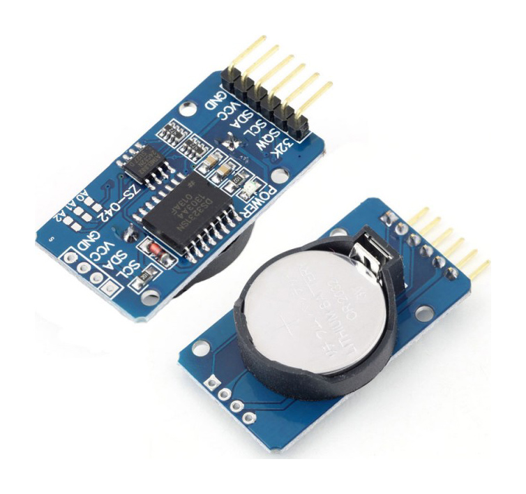
To get an Arduino setup with the DS3231 RTC and sleeping, check out this simple instructable. Long story short, you will need the RTC extended library by Fabio Cuomo and Rocket Scream's Low-Power library. Then, you can run this code to test the functionality.
#include "Wire.h"
#include "RTClibExtended.h"
#include "LowPower.h"

#define wakePin 2    //use interrupt 0 (pin 2) and run function wakeUp when pin 2 gets LOW
#define ledPin 13    //use arduino on-board led for indicating sleep or wakeup status

RTC_DS3231 RTC;      //we are using the DS3231 RTC

byte AlarmFlag = 0;
byte ledStatus = 1;

//-------------------------------------------------

void wakeUp()        // here the interrupt is handled after wakeup
{
}

//------------------------------------------------------------

void setup() {
  //Set pin D2 as INPUT for accepting the interrupt signal from DS3231
  pinMode(wakePin, INPUT);

  //switch-on the on-board led for 1 second for indicating that the sketch is ok and running
  pinMode(ledPin, OUTPUT);
  digitalWrite(ledPin, HIGH);
  delay(1000);

  //Initialize communication with the clock
  Wire.begin();
  RTC.begin();
  RTC.adjust(DateTime(__DATE__, __TIME__));   //set RTC date and time to COMPILE time

  //clear any pending alarms
  RTC.armAlarm(1, false);
  RTC.clearAlarm(1);
  RTC.alarmInterrupt(1, false);
  RTC.armAlarm(2, false);
  RTC.clearAlarm(2);
  RTC.alarmInterrupt(2, false);

  //Set SQW pin to OFF (in my case it was set by default to 1Hz)
  //The output of the DS3231 INT pin is connected to this pin
  //It must be connected to arduino D2 pin for wake-up
  RTC.writeSqwPinMode(DS3231_OFF);

  //Set alarm1 every day at 18:33
  RTC.setAlarm(ALM1_MATCH_HOURS, 33, 18, 0);   //set your wake-up time here
  RTC.alarmInterrupt(1, true);
}

//------------------------------------------------------------

void loop() {
  //On first loop we enter the sleep mode
  if (AlarmFlag == 0) {
    attachInterrupt(0, wakeUp, LOW);                       //use interrupt 0 (pin 2) and run function wakeUp when pin 2 gets LOW
    digitalWrite(ledPin, LOW);                             //switch-off the led for indicating that we enter the sleep mode
    ledStatus = 0;                                         //set the led status accordingly
    LowPower.powerDown(SLEEP_FOREVER, ADC_OFF, BOD_OFF);   //arduino enters sleep mode here
    detachInterrupt(0);                                    //execution resumes from here after wake-up

    //When exiting the sleep mode we clear the alarm
    RTC.armAlarm(1, false);
    RTC.clearAlarm(1);
    RTC.alarmInterrupt(1, false);
    AlarmFlag++;
  }

  //cycles the led to indicate that we are no more in sleep mode
  if (ledStatus == 0) {
    ledStatus = 1;
    digitalWrite(ledPin, HIGH);
  }
  else {
    ledStatus = 0;
    digitalWrite(ledPin, LOW);
  }

  delay(500);
}
While that code works great for one time alarms, I want the alarm to be automatically set at an interval. To do so, modify the above code by deleting the preset alarms and injecting this code.
byte logInterval = 20;  //number of minutes between alarms

//Set alarm some time from now
DateTime now = RTC.now(); //check the time

hours = now.hour();
minutes = logInterval - (now.minute() % logInterval) + now.minute();
if (minutes > 59)  //count minutes by 60
{
  minutes -= 60;
  hours++;
}
if (hours > 23 ) hours -= 24;  //count hours by 24

RTC.setAlarm(ALM1_MATCH_HOURS, minutes, hours, 0);   //set your wake-up time here
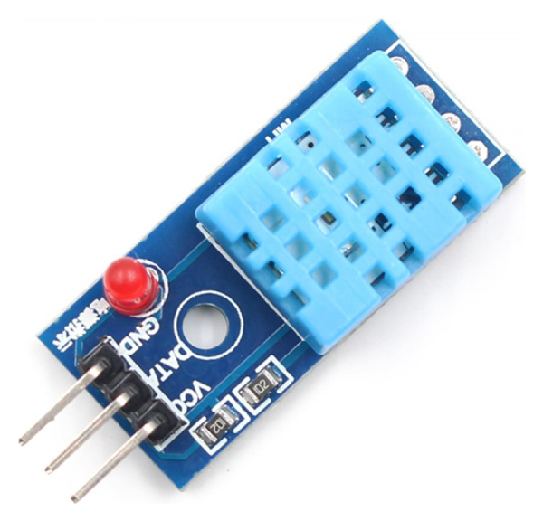
The DHT-11 is a temperature and humidity sensor which provides a digital signal of it's readings. The sensor works on 3 - 5V. I am using it at 3.3V on the same power output as the ESP8266. Here is a link to the DHT sensor library. Call out the type of DHT sensor you have and it's pin. Then use one of two commands.
#include "DHT.h"                //DHT11 Temperature | Humidity Sensor
DHT dht(3, DHT11);
float temp = dht.readTemperature();
float humid = dht.readHumidity();
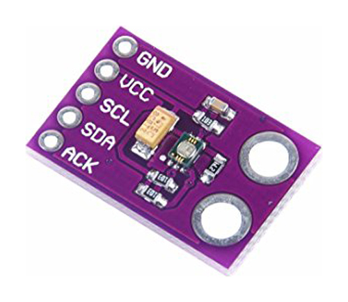
CJMCU-6070 UV sensor works across I2C and 3 - 5V. I chained it with the DS3231 and connected to the power output of the LM1117. Adafruit has a thorough walkthrough of its operation. Or, you can simply connect it to your Arduino and use this library. You'll just need three lines of code.
#include "Adafruit_VEML6070.h"  //CJMCU-6070 UV sensor
Adafruit_VEML6070 uv = Adafruit_VEML6070();
float uv = uv.readUV();
I only want to take environmental readings at an interval of time and to conserve on battery power, I put the Arduino to sleep. Every other component aside from the DS3231 does not need power either. All the other components are working on 3.3 volts and powered through the voltage regulator. So, I added an PN2222A NPN transistor to disconnect the regulator from power while the Arduino is sleeping.
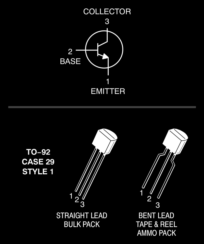
The collector is connected to the raw voltage. Emitter goes to the V.IN pin of the voltage regulator. And the base is connected to an Arduino DIO pin through a 1000Ω resistor. When a signal is sent to the base, the collector connects to the emitter. That simple.
Thing Speak is an open Internet of Things (IoT) web platform. You can use it to send and receive data to your internet connected devices. I set up a free channel for logging data for the Pure Imagination project. That channel is here. Setup an account, create a new channel then grab the API Key for that channel. You will need that to identify where to log data when communicating with Thing Speak. With all that stuff, you can use this code to test (assuming use of an ESP8266).
//Libraries------------------------------------------------------------------------------------------
#include "SoftwareSerial.h"

SoftwareSerial espSerial(4, 5);  //arduino RX pin=4, arduino TX pin=5  RX pin to esp8266 TX pin | TX pin to esp8266 RX pin

String network = "wifiNetowrk";
String password = "password";
String apiKey = "thingspeak API string here";
#define server "184.106.153.149"

const bool DEBUG = true;
const int serverDelay = 250;

//Variables
int testValue1 = 10;
int testValue2 = 20;
const long postInterval = 20000;   //Thing Speak requires at least 20 seconds between uploads

//SETUP----------------------------------------------------------------------SETUP
void setup() {
  Serial.begin(9600);

  //uncomment these lines to reset the module to 9600 baud rate permanently
  /*
  espSerial.begin(115200);
  espSerial.println("AT+RST");         // Enable this line to reset the module;
  showResponse(1000);
  espSerial.println("AT+UART_DEF=9600,8,1,0,0");    // Enable this line to set espSerial serial speed to 9600 bps
  showResponse(1000);
  Serial.println("espSerial baud switch");
  */

  espSerial.begin(9600);    //change the arduino software serial baud rate to something it can understand <= 57600
  espSerial.println("AT+CWMODE=1");   // set esp8266 as client
  showResponse(1000);
  espSerial.println("AT+CWJAP=\""+network+"\",\""+password+"\"");  // set your home router SSID and password
  bool wifi = showResponse(5000);
  if (wifi) Serial.println("wifi connected");
}

//LOOP-------------------------------------------------------------------------LOOP
void loop() {
    bool datalog = thingSpeakWrite(testValue1, testValue2);
    if (datalog) Serial.println("thingspeak successful");
    delay(postInterval);
}

//THINGSPEAK COMMUNICATIONS-----------------------------------------------------------THINGSPEAK COMMUNICATIONS
bool thingSpeakWrite(float value1, float value2){
//Build string for connecting to thingspeak
  String cmd = "AT+CIPSTART=\"TCP\",\"";                  // TCP connection
  cmd += server;                               // api.thingspeak.com
  cmd += "\",80";

  espSerial.println(cmd);
  if (DEBUG) Serial.println(cmd);
  delay(serverDelay);  //adjust delay according to server comms
  if (espSerial.find("Error"))
  {
    if (DEBUG) Serial.println("AT+CIPSTART error");
    return false;
  }

  //build a string for which channel and what data
  String getStr = "GET /update?api_key=";   // prepare GET string
  getStr += apiKey;

  getStr +="&field1=";
  getStr += String(value1);
  getStr +="&field2=";
  getStr += String(value2);
  // getStr +="&field3=";
  // getStr += String(value3);
  // ...
  getStr += "\r\n\r\n";

  //prepare thingspeak with data length to confirm
  cmd = "AT+CIPSEND=";
  cmd += String(getStr.length());
  espSerial.println(cmd);
  if (DEBUG)  Serial.println(cmd);

  delay(serverDelay);

  if(espSerial.find(">"))
  {
    espSerial.print(getStr);
    if (DEBUG) Serial.print(getStr);
  }
  else
  {
    espSerial.println("AT+CIPCLOSE");
    if (DEBUG)   Serial.println("AT+CIPCLOSE error");
    return false;
  }
  return true;
}

//SHOW RESPONSE------------------------------------------------------------SHOW RESPONSE
bool showResponse(int waitTime)
{
  long t = millis();
  char c = "a";
  while (t + waitTime > millis())
    if (espSerial.available())
    {
      c = espSerial.read();
      if (DEBUG) Serial.print(c);
      if (espSerial.find("P") || espSerial.find("K")) return true;
    }
  return false;
  }
Finally, I pulled all those pieces of code together. In this version, the arduino wakes at 00 20 and 40 minutes, attempts to connect to wifi, and if it succeeds, it reads data from the three sensors and attempts to send that information to Thing Speak.
/*
Wake, log sensor data to thingspeak.com, then sleep
J.travis russett
*/
//Libraries-----------------------------------------------------------------------------Libraries
#include "SoftwareSerial.h"     //Software Serial (for ESP8266 Comms)
#include "Wire.h"               //I2C
#include "RTClibExtended.h"     //DS3231 Real-Time Clock
#include "LowPower.h"           //Alarm interrupts with DS3231 RTC
#include "DHT.h"                //DHT11 Temperature | Humidity Sensor
#include "Adafruit_VEML6070.h"  //CJMCU-6070 UV sensor

//Library calls----------------------------------------------------------------------Library calls
RTC_DS3231 RTC;
SoftwareSerial espSerial(4, 5);  //arduino RX pin=4, arduino TX pin=5  RX pin to esp8266 TX pin | TX pin to esp8266 RX pin
Adafruit_VEML6070 uv = Adafruit_VEML6070();
DHT dht(3, DHT11);  //DHT11 (Pin, Type)

const int wakePin = 2;    //use interrupt 0 (pin 2) and run function wakeUp when pin 2 gets LOW
const int vReg = 12;  //Transistor

//Things speak stuff
String network = "yourNetwork";
String password = "yourPassword";
String apiKey = "yourAPI";
#define server "184.106.153.149"
unsigned int serverDelay = 250; //delay for serial comms 250 is consistent, 200 misses connections
bool dataLog = true;
bool wifiConnect = true;
int minutes;
int hours;

const int numberOfReadings = 100;  //sensor reads to be averaged, data smoothing
byte logInterval = 20;  //number of minutes between thingspeak data logs
byte wifiErrorInterval = 5;
const bool DEBUG = true;

//Function declarations
bool esp01Connect();
bool showResponse(int waitTime);
bool thingSpeakWrite(float field1, float field2, float field3);
float getEnvironSensorValue(int sensorToRead);
void wakeUp();

//SETUP----------------------------------------------------------------------SETUP
void setup() {
  Serial.begin(9600);
  //enable this to reset the ESP8266 module to 9600 BAUD permanently
  /*
  espSerial.begin(115200);
  espSerial.println("AT+RST");         // Enable this line to reset the module;
  showResponse(1000);
  espSerial.println("AT+UART_DEF=9600,8,1,0,0");    // Enable this line to set espSerial serial speed to 9600 bps
  showResponse(1000);
  */
  espSerial.begin(9600);  //this speed works for ESP comms

  //slow clock to 1mHz
  //CLKPR = 0x80;
  //CLKPR = 0x04;

  //enable the 3.3V flow through transistor
  pinMode(vReg, OUTPUT);

  //Set pin D2 as INPUT for accepting the interrupt signal from DS3231
  pinMode(wakePin, INPUT);

  //Initialize communication with the clock
  Wire.begin();
  RTC.begin();
  RTC.adjust(DateTime(__DATE__, __TIME__));   //set RTC date and time to COMPILE time

  //clear any pending alarms
  RTC.armAlarm(1, false);
  RTC.clearAlarm(1);
  RTC.alarmInterrupt(1, false);
  //RTC.armAlarm(2, false);
  //RTC.clearAlarm(2);
  //RTC.alarmInterrupt(2, false);

  //Set SQW pin to OFF (in my case it was set by default to 1Hz)
  //The output of the DS3231 INT pin is connected to this pin
  //It must be connected to arduino D2 pin for wake-up
  RTC.writeSqwPinMode(DS3231_OFF);
}


//LOOP-------------------------------------------------------------------------LOOP
void loop()
{
  //Set alarm some time from now
  DateTime now = RTC.now(); //check the time.
  if (dataLog && wifiConnect)
  {
    hours = now.hour();
    minutes = logInterval - (now.minute() % logInterval) + now.minute();
  }
  else
  {
    hours = now.hour();
    minutes = wifiErrorInterval + now.minute();
  }

  if (minutes > 59)  //count minutes by 60
  {
    minutes -= 60;
    hours++;
  }
  if (hours > 23) hours -= 24;  //count hours by 24

  if (DEBUG) Serial.println(String(hours) + ":" + String(minutes));

  RTC.setAlarm(ALM1_MATCH_HOURS, minutes, hours, 0);   //set your wake-up time here
  RTC.alarmInterrupt(1, true);

  //Engage sleep mode on first loop
  attachInterrupt(0, wakeUp, LOW);                       //use interrupt 0 (pin 2) and run function wakeUp when pin 2 gets LOW
  if (DEBUG)
  {
    Serial.println("sleep");
    delay(100);
  }
  LowPower.powerDown(SLEEP_FOREVER, ADC_OFF, BOD_OFF);   //arduino enters sleep mode here
  detachInterrupt(0);                                    //execution resumes from here after wake-up

  //When exiting the sleep mode clear the alarm
  RTC.armAlarm(1, false);
  RTC.clearAlarm(1);
  RTC.alarmInterrupt(1, false);
  if (DEBUG) Serial.println("wake");

  digitalWrite(vReg, HIGH);  //3.3V open
  delay(500);  //wait a moment for voltage to fill caps

  //connect to wifi first, if it fails, skip everything else...
  int j = 0;
  do
  {
    wifiConnect = esp01Connect();
    j++;  //safety valve
    if (DEBUG) Serial.println((3 - j) + "...");
  }
  while(!wifiConnect && j < 3);
  if(DEBUG && !wifiConnect) Serial.println("wifi failed");

  if(wifiConnect)
  {
    if (DEBUG) Serial.println("wifi connected");
    //collect UV, temp and humidity data
    float UV = getEnvironSensorValue(2); // read average UV value
    float temp = getEnvironSensorValue(0);  // read average temperature value
    float humidity = getEnvironSensorValue(1); // read average humdity value

    //Log data to thingspeak.com
    dataLog = thingSpeakWrite (temp, humidity, UV);
    if (DEBUG) Serial.println(dataLog);
  }

  digitalWrite(vReg, LOW);  //3.3V closed
}

//ENVIRONMENTAL SENSOR DATA COLLECTION-----------------------------------------------------I2C SENSOR DATA COLLECTION
float getEnvironSensorValue(int sensorToRead)
{
  //make variables and read sensor
  float runningValue = 0;
  float reading;
  for(int x = 0 ; x < numberOfReadings ; x++)
  {
    do
    {
      if (sensorToRead == 0) reading = dht.readTemperature();  //read the temperature sensor
      if (sensorToRead == 1) reading = dht.readHumidity();    //read the humidity sensor
      if (sensorToRead == 2) reading = uv.readUV();  //read the UV sensor
      delay(10);
      if(!(reading == reading)) delay (1000);
    }
    while(!(reading == reading));  //if reading is "nan" try again
    runningValue += reading;
  }
  runningValue /= numberOfReadings; //generate an average
  if (DEBUG) Serial.println(String(sensorToRead) + " " + String(runningValue));
  return(runningValue);
}

//THINGSPEAK COMMUNICATIONS-----------------------------------------------------------THINGSPEAK COMMUNICATIONS
bool thingSpeakWrite(float field1, float field2, float field3)
{
  //Build string for connecting to thingspeak
  String cmd = "AT+CIPSTART=\"TCP\",\"";                  // TCP connection
  cmd += server;                               // api.thingspeak.com
  cmd += "\",80";

  espSerial.println(cmd);
  if (DEBUG) Serial.println(cmd);
  delay(serverDelay);  //adjust delay according to server comms
  if (espSerial.find("Error"))
  {
    if (DEBUG) Serial.println("AT+CIPSTART error");
    return false;
  }

  //build a string for which channel and what data
  String getStr = "GET /update?api_key=";
  getStr += apiKey;
  getStr +="&field1=";
  getStr += String(field1); //temp
  getStr +="&field2=";
  getStr += String(field2); //humidity
  getStr +="&field3=";
  getStr += String(field3); //UV
  getStr += "\r\n\r\n";

  //prepare thingspeak with data length to confirm
  cmd = "AT+CIPSEND=";
  cmd += String(getStr.length());
  espSerial.println(cmd);
  if(DEBUG) Serial.println(cmd);

  delay(serverDelay); //adjust delay according to server comms

  if (espSerial.find(">"))  //if thingspeak responds, send data
  {
    espSerial.print(getStr);
    if (DEBUG) Serial.print(getStr);
  }
  else  //otherwise, end transmission
  {
    espSerial.println("AT+CIPCLOSE");
    if (DEBUG) Serial.println("AT+CIPCLOSE error");
    return false;
  }
  return true;
}

//ESP-01 ENGAGE------------------------------------------------------------ESP-01 ENGAGE
bool esp01Connect()
{
  bool connectStatus;
  //connect esp-01 to wifi
  //if having comms issues, check setup to reset BAUD rate
  espSerial.println("AT+CWMODE=1");   // set esp8266 as client
  showResponse(1000);
  espSerial.println("AT+CWJAP=\""+network+"\",\""+password+"\"");  // set your home router SSID and password
  connectStatus = showResponse(10000);
  if (DEBUG) Serial.println();
  if (!connectStatus) return false;
  return true;
}

//SHOW RESPONSE------------------------------------------------------------SHOW RESPONSE
bool showResponse(int waitTime)
{
  long t = millis();
  char c = "a";
  while (t + waitTime > millis())
    if (espSerial.available())
    {
      c = espSerial.read();
      if (DEBUG) Serial.print(c);
      if (espSerial.find("P") || espSerial.find("K")) return true;
    }
  return false;
}

void wakeUp()        // here the interrupt is handled after wakeup
{
}
These are the environmental Thing Speak charts. They may still be live...
I added some sensor smoothing, but it is not working 100% yet because I still get some odd readings. I am considering adding in a check to see what percentage difference one reading is from the previous to force another set of readings. Or, I think sometimes the DHT-11 is sending readings of "0" which is weighing down my average. So maybe another thing to do would be to filter any readings outside of a range of from the mean.
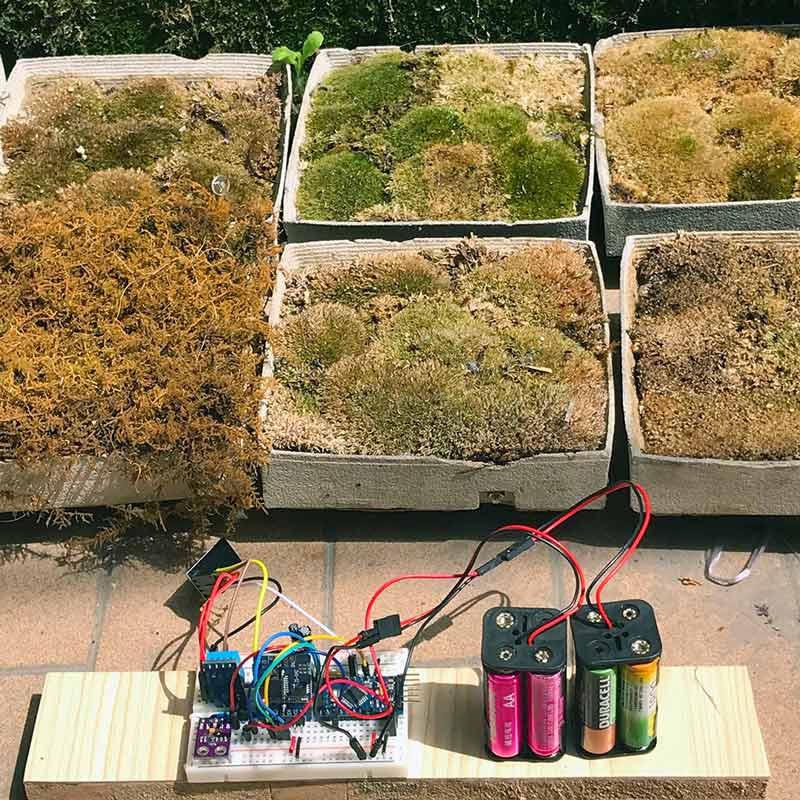
I did terribly caring for my moss over the winter...
I will post links to resources I have found helpful here.
Share this post...
« Previous post :: Distributed Version Control : GIT
Git is an actively maintained, free and open source, distributed version control system originally developed in 2005 by Linus Torvalds (Linux). Distributed version control systems help software development teams collaborate on projects' source code by maintaining a full history of file changes across a decentralized file system. The distributed architecture maintains a full history of all changes in every developer's local working directory, aka repository. Redundancy. Git is flexible. Git works across all platforms, supports branching and tagging as first class citizens and operations within, such as merging or reverting. Open sites such as GitHub or GitLab are fantastic for...
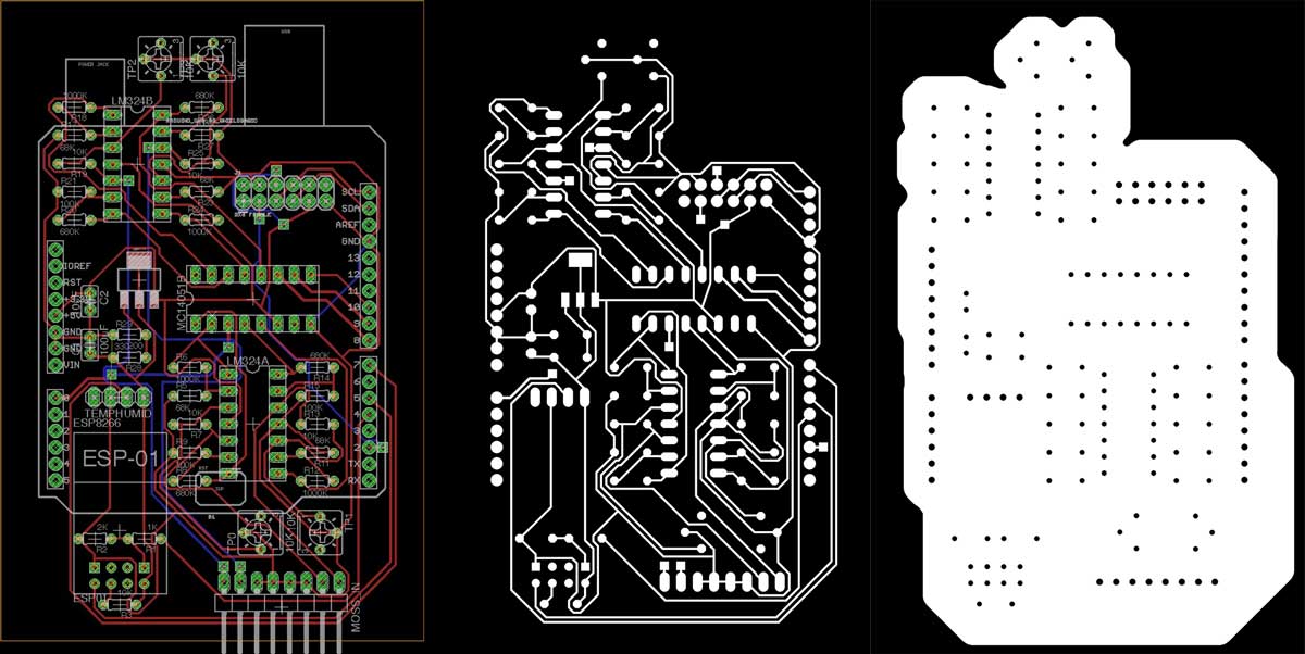
Next post :: Eagle : Export PCBs quickly with this script »
Exporting image files for milling PCBs is a tedious operation. Fortunately, Eagle has a built-in scripting interface. Customized scripts, spanning multitudes of operations, can be launched from the file menu. The following script, based on this one, will output two PNGs, one for traces and the other for the outline and holes. The PNGs can then be coverted to milling tool paths via Fab Modules. DISPLAY ALL; RATSNEST; DISPLAY None; DISPLAY Top Pads Vias; SET DISPLAY_MODE NODRILL; SET PAD_NAMES OFF; SET PALETTE BLACK; EXPORT IMAGE /*/pcb_traces.png MONOCHROME 1500; DISPLAY None; SET DISPLAY_MODE REAL; DISPLAY Pads; EXPORT IMAGE /*/pcb_outline.png MONOCHROME 1500;...