Tags
#chemistry
#biology
#pureImagination
#science
Pure Imagination
- Environmental monitoring with online data logging to Thingsv
- Inventory
- Hessian/ burlap/ crocus composites
- CNC milled wood frame
- Grow monitors | What watches the watchers?
- Grow module | Design and fabrication
- Grow Module | The science
- Processing Light Graph
- Milling a composite mold
- Composites : Modular growth, testing
- Bio-electro-chemistry
- Bioelectrochemical testing pod
- LCD x Arduino
- Precedents
- Discussion
- Design, Materials and Methods
- History : Early concepts
2017 May 31
#chemistry
#biology
#pureImagination
#science
The nonvascular bryophyte microbial fuel cell operates in two main zones: anode and cathode. The anode side is a layer of moss, two mixtures of cotton and carbon (10:1, cotton : carbon weight) sandwiching a single layer of stainless steel mesh (as thin as possible). This anode mixture is from the 2016 October 3 Royal Society published work of Paolo Bombelli, et al. Electrical output of bryophyte microbial fuel cell systems is sufficient to power a radio or an environmental sensor.
The cathode is a sandwich of acrylic (bread), rubber (condiment), hydrogen electrode (10 wt % Pt/C + 5% Nafion solution + wet-proofed carbon cloth) and another stainless steel mesh. This cathode preparation is based on the work of Shaoan Cheng, et al. Power Densities Using Different Cathode Catalysts (Pt and CoTMPP) and Polymer Binders (Nafion and PTFE) in Single Chamber Microbial Fuel Cells published in Environmental Science and Technology, 2006 January.
The following illustration is from the previously linked Bombelli research report. It may not be cool according to copyright. Irregardless, I will replace it with one of my own soon. This is not my illustration but the general setup of a module is the same.

First I prepared the cathode. A catalyst is applied to the cathode and needs 24 hours in room temperature to cure.
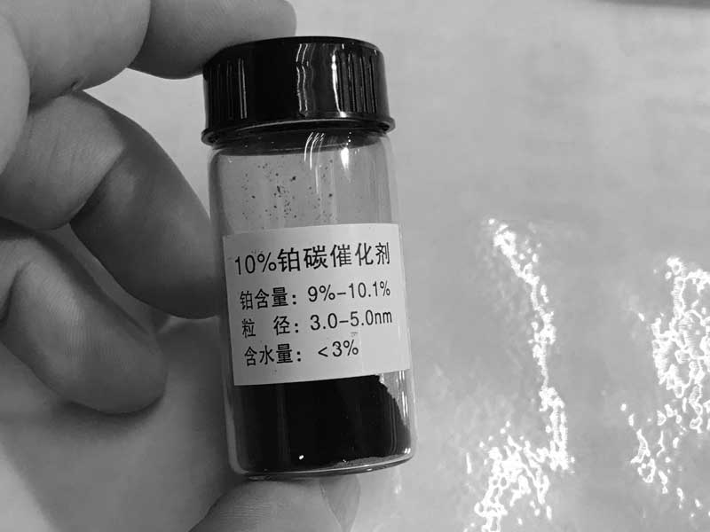
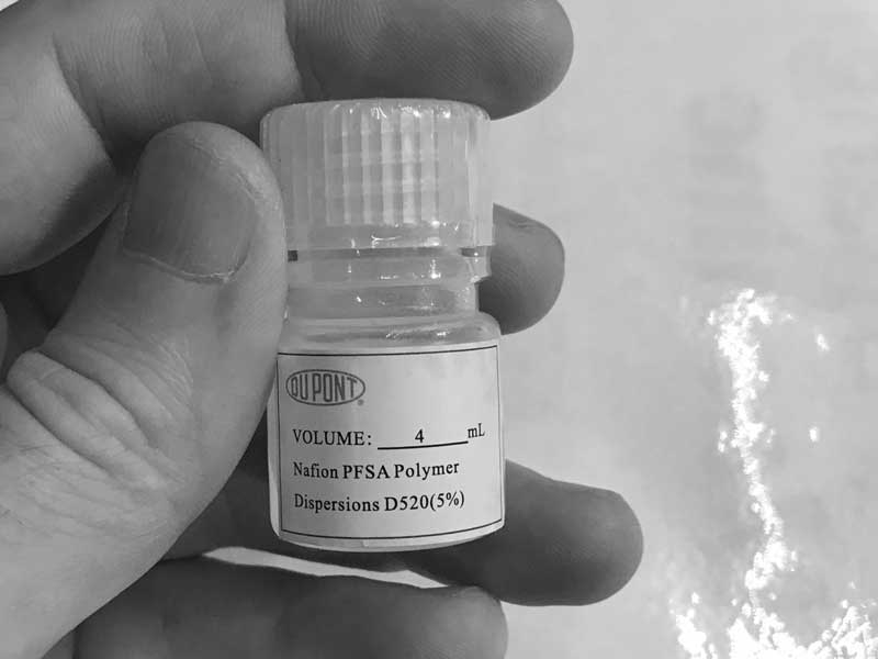
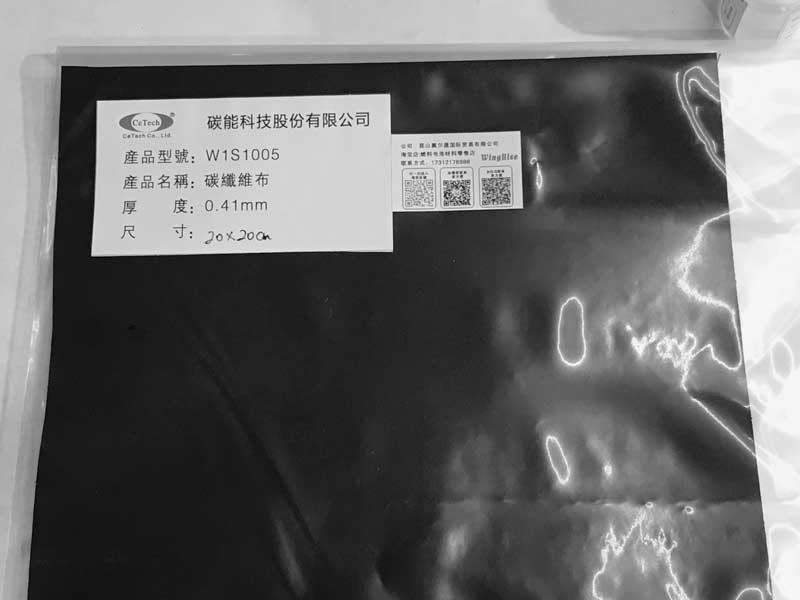
A commercial Pt catalyst (10 wt % Pt/C) was mixed with a chemical binder (5% Nafion solution) to form a paste (7 μL of binder per mg of Pt/C catalyst). The paste was applied to one side of the wet-proofed carbon cloth (CaTech, 0.41mm, W1S1005). The Pt content was approximated at 0.5mg cm-2.
| 100 square millimters wet-proofed carbon fabric | 0.5mg Pt 5mg 10 wt % Pt/C 2.5mg 20 wt % Pt/C |
35μL Nafion (10 wt % Pt/C) 17.5μL Nafion (20 wt % Pt/C) |
|---|
1g 10 wt % Pt/C
0.41mm Wet-proofed Carbon Fabric W1S1005
Small measuring tools. None of these materials are toxic but the platinum powder is precious and the carbon is messy. So I wear gloves.
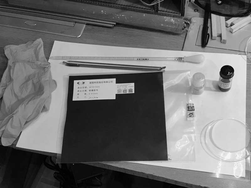
I mix the Nafion with the Pt/C powder in this dish.
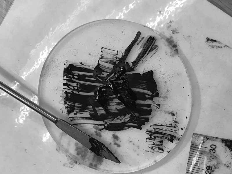
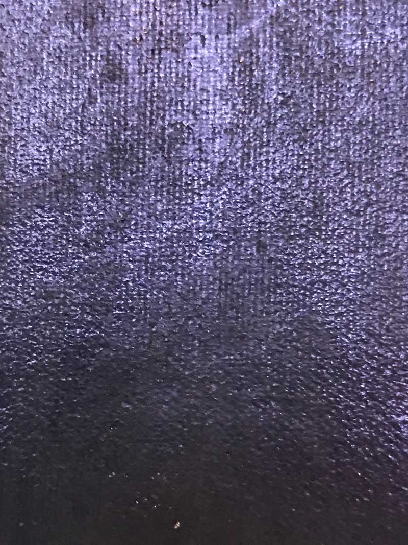
Then I scrape the resultant paste onto the fabric and set it aside for one day to bond the materials.
This is not me. The video is similar in process.
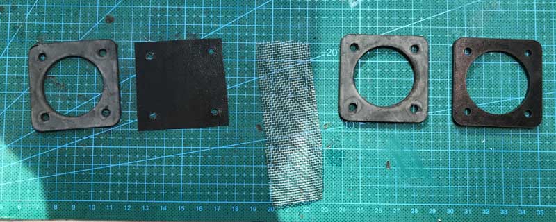
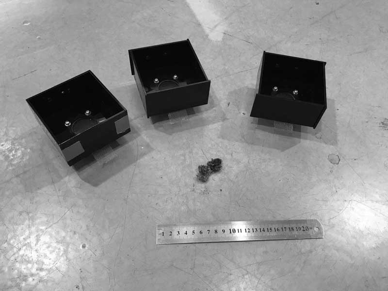
Flash forward one day. I sourced some rubber sheet material and cut that and acrylic for the custom components of the cathode side of the module.
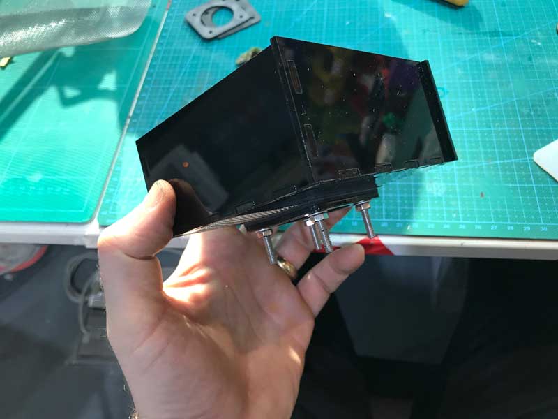
And that assembled looks like this. The cathode connection will occur on the stainless steel. Be aware of the alignment of that with the anode of this module and others, depending on the module configuration.
Three testing modules are ready for anode mixture and more moss.
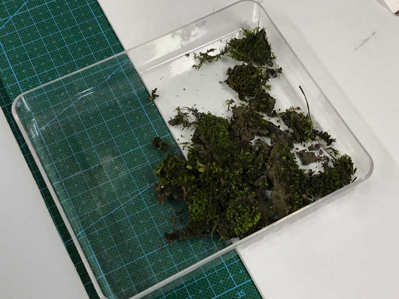
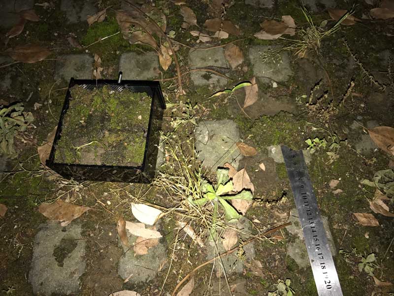
Just before I started preparing the anode, I locally sourced moss. For the final outcome, I may source a wider variety of moss from an online retailer in Shanghai.
Now that I know where I will collect the moss. I am ready to prepare the anode mixture.
| 1000 cubic millimeters | This much cotton by weight | 1/10th of that weight in carbon fiber. |
|---|
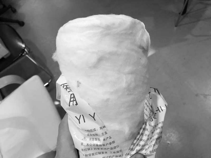
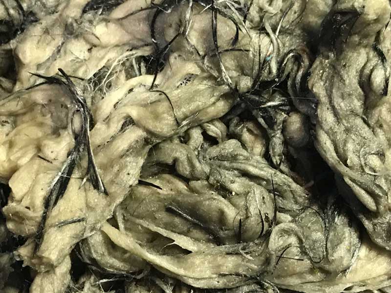
Cotton
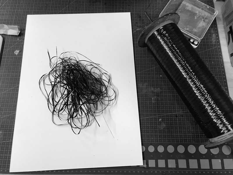
Carbon fiber. When cut into small pieces, this material is dangerous for your skin, eyes, lungs, everything. Cover all your skin, mouth and eyes. Do not be careless.
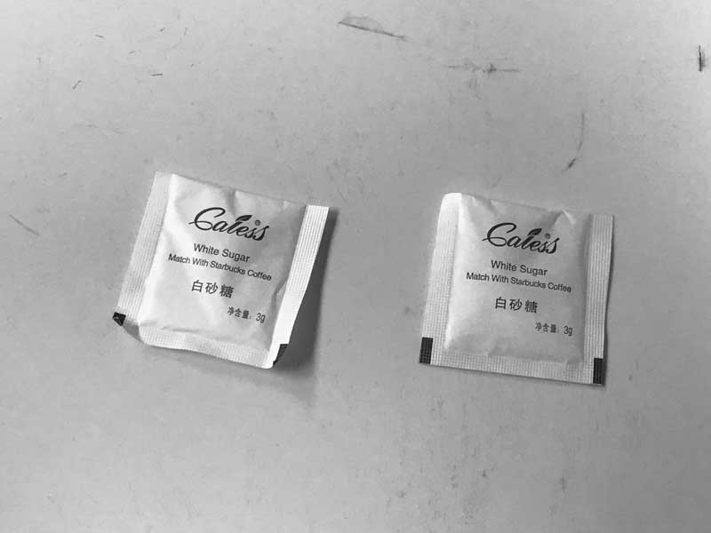
Starbucks sugar
Moss
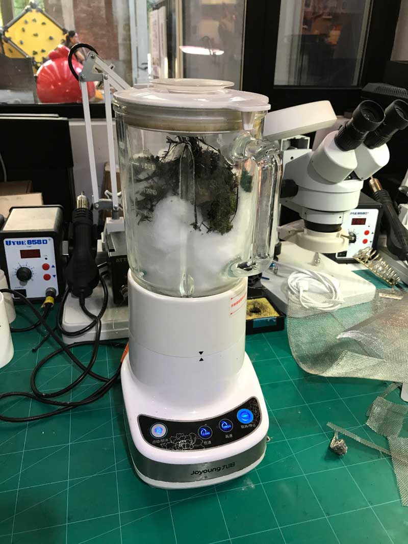
Combine all these with some water. I used a blender which was not great for the cotton. In the following iterations, I will likely pull the cotton apart by and and toss the materials together by hand.
Lay some tissue, preferably cotton tissue, on the bottom of the module.
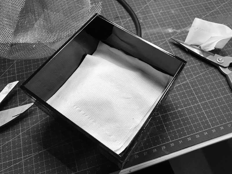
Fill halfway with the anode mixture. On top of this, lay a layer of stainless steel mesh. I forgot to take a photo of this part.
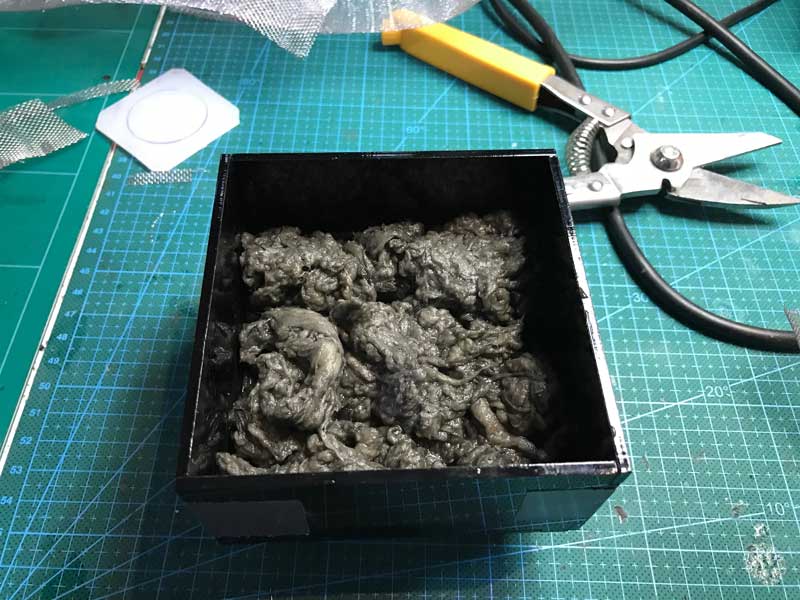
Fill nearly to the top with more anode mixture.
Finally, transplant moss. Be gentle. And water generously.
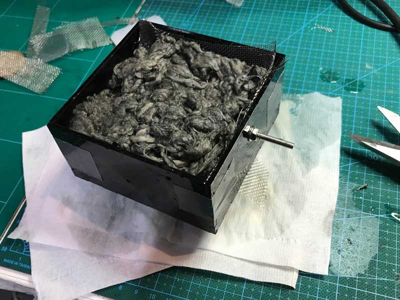
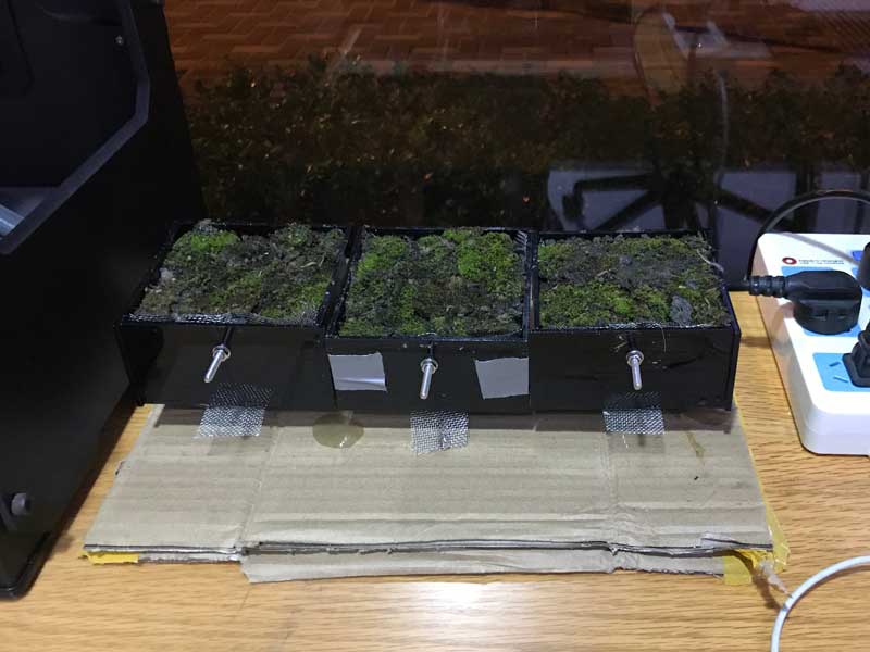
Three testing modules that I hope will soon begin outputing electricity.
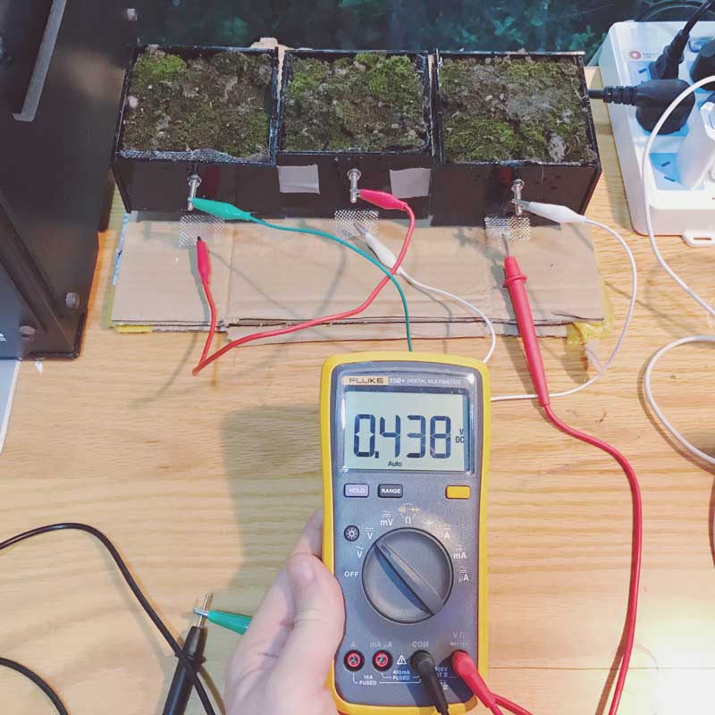
The next day, the modules were already outputting electricity. On the second day, when I returned to the lab the modules connected in series were outputting 438mV at 30uA and I am psyched.
Share this post...
« Previous post :: Infrared networking
Now I that I have a master-slave network setup, I would like to see if I can get the two boards to send signals back and forth autonomously. First, I extended the sensor test sketch to react via its LED and the serial monitor. I kept the serial monitor so I could debug along the way. One board is transmitting IR signals at random intervals. The other board is checking the IR receiver and when a signal is sensed, it triggers the LED on the board to illuminate for a short time period, then resumes loking. First the code for...
Next post :: Fireflies and grasshoppers. »
I would like to start with the Firefly plugin in Grasshopper and see if I can control a stepper motor. If I can get a successful start with that, then I might be able to incorporate dishuBot controls through Grasshopper/ Firefly rather than GRBL. This would be directly connected to my G-code transcoder. There are a few challenges. One, Firefly has not been released on the MacOS, my operating system. Two, I need to learn to setup code for the board to accept commands through serial from Firefly. This is an example of Firefly reading and parsing live hand tracking...