Tags
#cut2d
#coding
#pureImagination
#CCC
Pure Imagination
- Environmental monitoring with online data logging to Thingsv
- Inventory
- Hessian/ burlap/ crocus composites
- CNC milled wood frame
- Grow monitors | What watches the watchers?
- Grow module | Design and fabrication
- Grow Module | The science
- Processing Light Graph
- Milling a composite mold
- Composites : Modular growth, testing
- Bio-electro-chemistry
- Bioelectrochemical testing pod
- LCD x Arduino
- Precedents
- Discussion
- Design, Materials and Methods
- History : Early concepts
2017 May 03
#cut2d
#coding
#pureImagination
#CCC
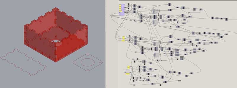
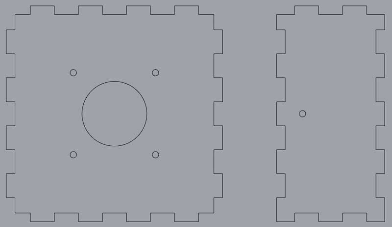
The fabrication demands of this project are far less than other aspects. Keep it simple. Spiral develop. I essentially want an open-faced cube in acrylic. I will develop a grasshopper, parametric model with variables for overall dimensions, finger joint size, laser kerf, bolt and other holes (unrelated to box adhesion).
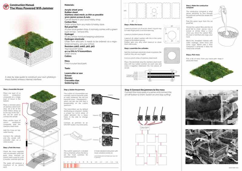
The prototype is based on the work of Paolo Bombelli, et al. This is the desired composition. The pot, plastic fixture and possibly rubber washers will be laser cut and Jakob Skote's Moss Powered Wifi Jammer project. Excellent work. Visit them.
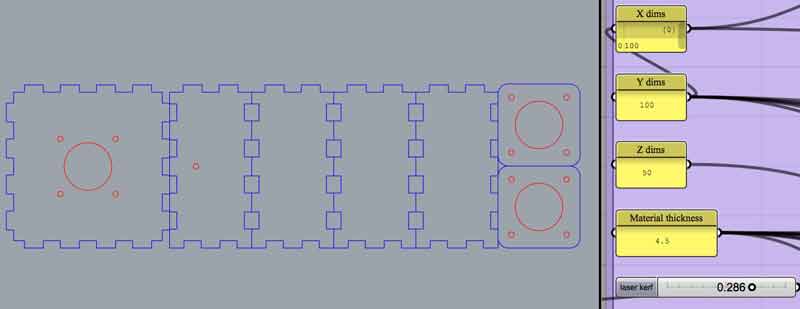
Fast-forward a little in time and I have a working grasshopper graph. This time I setup the file to automatically generate the linework for laser cutting. Next time, I would like to take it a step further and find an easy solution for optimally organizing the pieces. No doubt some clever folks have working solutions available in the web. The controls for most of the variables are in a small cluster.
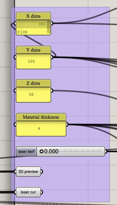
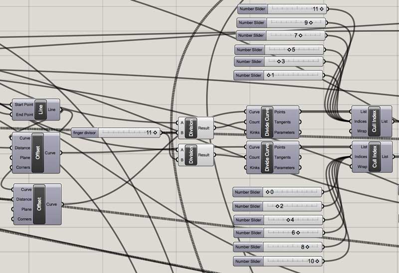
Currently, it is optimized for a square bottom although, changing for different X and Y lengths would not be difficult. In fact, the solution to that problem has already been incorporated in the "code" for the sides. I am enjoying learning this application. I know I am still only scratching the surface but with each of these projects I dive a little deeper. One of my weaknesses is working with indices. This for instance is the overwrought solution for the finger joints.
This grasshopper graph could be ported for a number of uses beyond making boxes as these pieces will connect in different configurations. Plus, by changing a couple numbers, other pieces will be made. I plan to build some boxes tomorrow.
Okay, back in the lab today and the laser cutter is free. First, I will build a prototype from cardboard. Cardboard cuts fast. Cardboard is cheap. Cardboard is plentiful. While it has more give than acrylic, I will be able to make some accurate predictions of how the acrylic will go together. The first thing I will do is a kerf test.
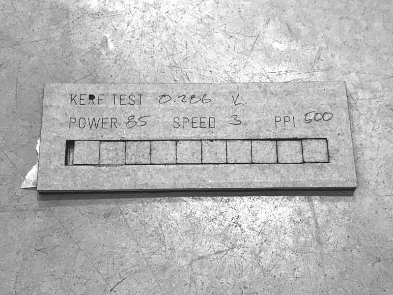
Using these settings and this material, I can expect an average of 0.286mm laser kerf. This cardboard is 4.5mm thick and tends to burn. Always keep an eye on it. I return to my grasshopper graph and input the values to adjust my model.
Moments later, back to the laser cutter to cut my first BPV module in cardboard.
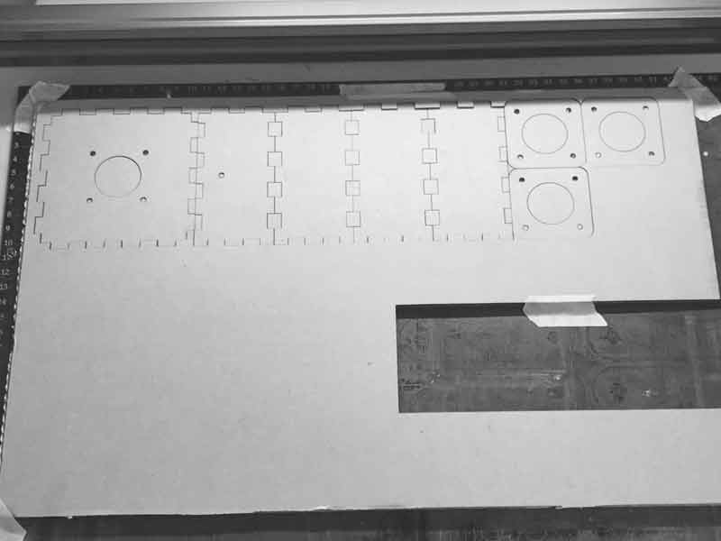
Then I clean up the material and try to assemble it. Nice tight fit. That might be an issue with acrylic because the cut tapers so I will need to be careful to measure kerf from the bottom side of the test. The bolts and nuts are for conducting cathode and anode, not box joints.
Update: I am now producing three water-proof boxes from acrylic for planting moss. I found some black 2.8mm thick stock. The laser kerf test with the settings below resulted in 0.0909, repeating of course, mm. I will set these values in Grasshopper and cut the boxes.
Speed: 1
PPI: 1000
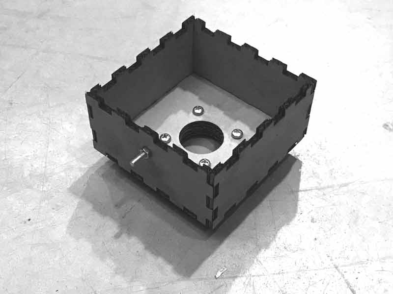
The first module.
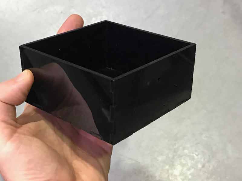
The second module. I was concerned that when filled, the walls may slide apart. So I iterated a bit on the fly.
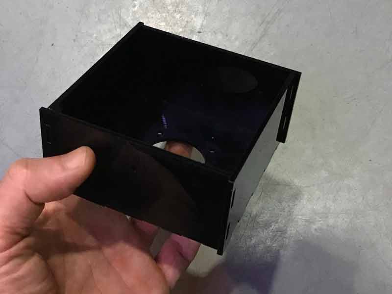
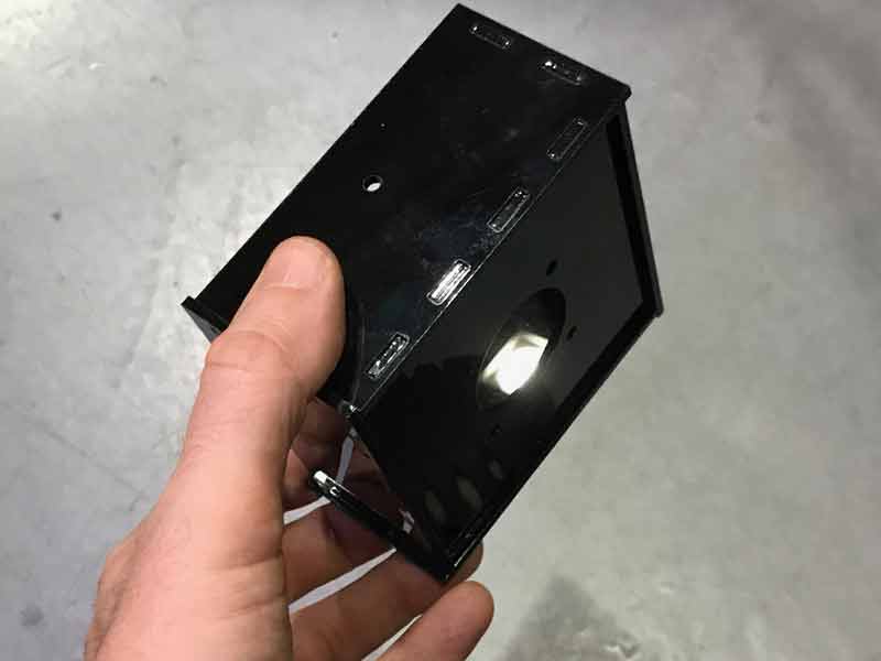
The third module. Then, I thought the bottom could be secured better, so I iterated again. By the time I arrived to this third box, it seems very secure. Regardless, I will make use of all three as the testing modules for my final work. What started as a generic press-fit kit could be quickly modified on the fly to address a specific use case.
Share this post...
« Previous post :: Phototransistor : reading
I will try a variety of programming languages until I get readings. I am pulling VCC and Ground connections from the ISP so my order of operations: program with my fabISP, disconnect fabISP and connect phototransistor VCC and GND. That looks like this. I thought this might be simple... I first tried this Arduino sketch for getting readings via the serial monitor. Unfortunately, I am not yet able to get any reading from the serial monitor, let alone light levels. // Using an ATTiny44 #include <SoftwareSerial.h> SoftwareSerial mySerial = SoftwareSerial (1,0); // RX PA1 12, TX PA0 13 // Pin...
Next post :: Composites : Modular growth, testing »
Composite materials are made of two or more constituent materials, each with significantly different, yet complimentary, physical and or chemical characteristics. When combined into a composite, the team of materials is greater than the sum of its components. I started the project by mocking up a form in Autodesk Maya. The form is like bamboo in that it grows in sections and has openings to contain the moss. At this point, rather than spending much time modeling this object, I would like to jump into making composites becasue it is my first time. This is a little mockup of what...