Tags
#coding
#electronics
#pureImagination microCode
- Environmental monitoring with online data logging to Thingsv
- Distributed Version Control : GIT
- Grow monitors | What watches the watchers?
- Fireflies and grasshoppers.
- Infrared networking
- Processing Light Graph
- Processing : coming around.
- Testing the electrical components of the IR network twins
- Chinese calligraphy G-code encoder
- Bio-electro-chemistry
- Phototransistor : reading
- Prototyping the effector
- LCD x Arduino
- Programming "Hello to the World" with C
- Fabricating a gestalt stage
- Breathing light : An arduino experiment
- Datasheet Atmel ATtiny24/44/84
- Echo : Programming.c
- Programming a programmer
- Arduino IDE, introduction
- Grasshopper Parametric Modeling
- HyperText Markup Language : HTML
- Cascading Style Sheets : CSS
- Eagle : Export PCBs quickly with this script
- Environmental monitoring with online data logging to Thingsv
- Grow monitors | What watches the watchers?
- Infrared networking
- Processing : coming around.
- Testing the electrical components of the IR network twins
- Chinese calligraphy G-code encoder
- Networking light : Twin PCB
- Phototransistor : reading
- Phototransistor breakout board
- EAGLE pt2 : Fabricating the circuit board
- Fabricating, wiring, learning
- LCD x Arduino
- LCD ATTiny44 PCB
- Programming "Hello to the World" with C
- Breathing light : An arduino experiment
- Datasheet Atmel ATtiny24/44/84
- EAGLE pt1 : Designing a circuit board
- Stuffing a circuit board
- Programming a programmer
- Milling a circuit board
- Design, Materials and Methods
- Phototransistor : reading
2017 May 02
#coding
#electronics
#pureImagination microCode
I will try a variety of programming languages until I get readings.
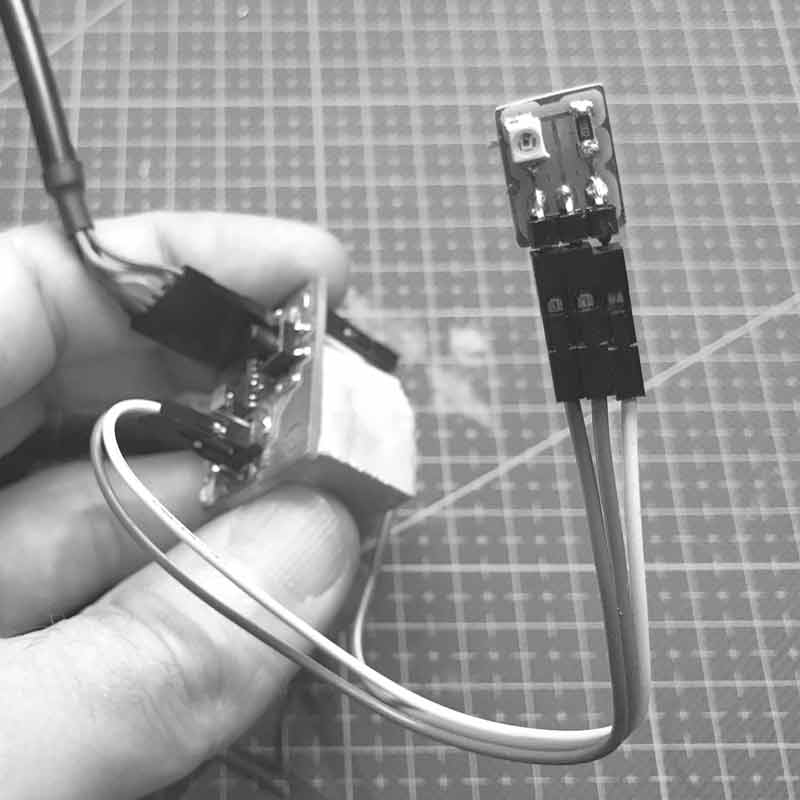
I am pulling VCC and Ground connections from the ISP so my order of operations: program with my fabISP, disconnect fabISP and connect phototransistor VCC and GND. That looks like this.
I thought this might be simple... I first tried this Arduino sketch for getting readings via the serial monitor. Unfortunately, I am not yet able to get any reading from the serial monitor, let alone light levels.
// Using an ATTiny44
#include <SoftwareSerial.h>
SoftwareSerial mySerial = SoftwareSerial (1,0);    // RX PA1 12, TX PA0 13

// Pin Configurations
const int SENSOR = A2;          // PA2
const int LED = A7;             // PA7
int sensorValue = 0;  // variable to store the value coming from the sensor


void setup() {
// declare the LED as an OUTPUT:
pinMode(LED, OUTPUT);
mySerial.begin(115200);
mySerial.println("I am here to serve.");
}

void loop() {                   // read the value from the sensor every 500 ms
sensorValue = analogRead(SENSOR);
mySerial.println(sensorValue);
digitalWrite(LED, HIGH);      // Blink LED for visualizing sensor timing
delay(250);
digitalWrite(LED, LOW);
delay(250);
}
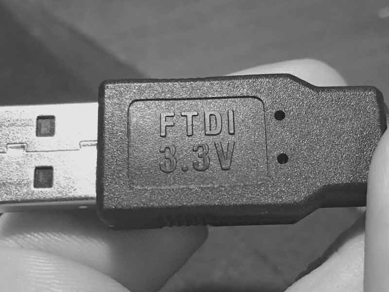
I tried to use a python serial monitor to no avail. Then, I returned to previous working code and uploaded the Echo : Hello World in C. This worked a few weeks ago in Python and Arduino serial monitors. Today, it is not working in either. I noticed that the FTDI serial number is different than the one I used previously. Upon inspecting the cable, I see it is 3.3Volts. I feel like I just wasted two hours. This project will have to wait until I return to the lab tomorrow to grab a 5V FTDI cable.
Upon returning to the lab, I switched to a 5V FTDI cable and confirmed the serial monitor working with the Echo: Hello World C program using a PySerial and Arduino Serial. Then I went about uploading an arduino sketch using Arduino's SoftwareSerial library. I wrote this for testing the serial.
// Using an ATTiny44
#include <SoftwareSerial.h>
SoftwareSerial mySerial(0,1);     // RX PA1 12, TX PA0 13 (flipped)

void setup() {
mySerial.begin(19200);          // start serial feed, set the baud rate
}

void loop() {                     // print hello every 250ms
mySerial.println("hello");
delay(250);
}
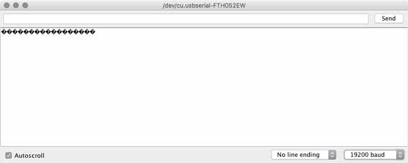
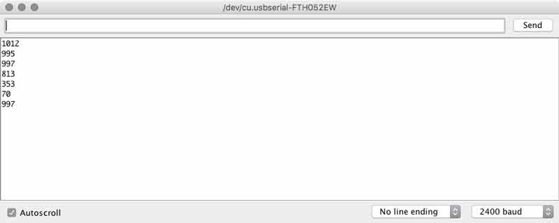
I was able to get readings from the serial monitor, but mostly black diamonds with a white question mark.
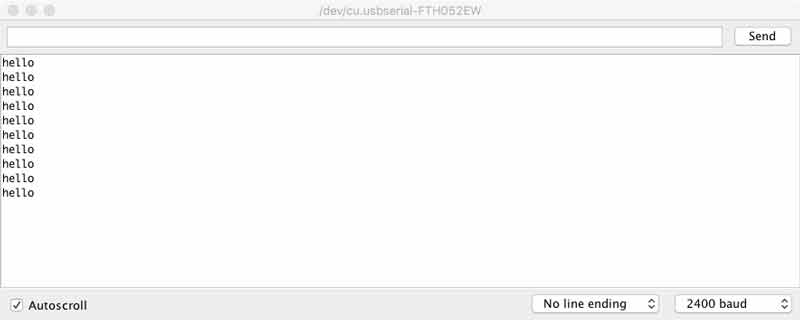
I thought something must be wrong with the baud rate so I began experimenting with different rates and also using the internal versus external clocks. By chance or shear exhaustion, I found setting the serial baud to 19200 in Arduino and 2400 on the serial monitor to report my expectation.
With those adjustments, I uploaded the previous code I modified for the phototransistor and it worked.
I noticed some students used a 49.9kOhm resistor on the Phototransistor to get more sensitive measurements. I replaced the 10KOhm resistor on my baord to see what would happen. This page explains the effect of resistors on phototransistors. With the same arduino code...
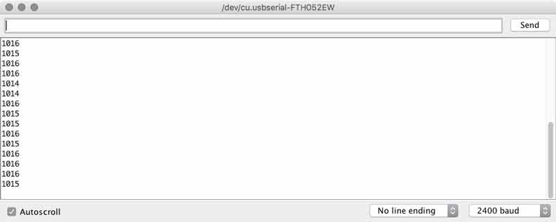
The range of readings from the brightest light to no light was only from 1011 to 1016. I checked the signal on our oscilliscope and found parity with the serial monitor. Then, in the process of tinkering I snapped the single pin header and much of the copper trace from my ATtiny44 board. While I was fixing that, I went back to the 10KOhm resistor on the phototransistor. We have adjustable resistors in the lab, it will be interesting to setup an experiment with one in the future.
I returned to the code and added a feature to convert the sensor values to a percentage of its total spectrum, making it easier to understand for us humans.
#include <SoftwareSerial.h>
SoftwareSerial mySerial(0,1);         // RX PA1 12, TX PA0 13 (flipped)

// Using an ATTiny44
// Pin Configurations
const int sensorPin = A2;             // PA2 11 ADC2
const int LED = A7;                   // PA7 6
int sensorValue = 0;                  // variable to store the value coming from the sensor
int outputValue = 0;                  // variable to store the PWM


void setup() {
pinMode(LED, OUTPUT);               // declare the LED as an OUTPUT:
mySerial.begin(19200);              // I set this to 19200 and arduino monitor to 2400
mySerial.println("Hello");
}

void loop() {
sensorValue = analogRead(sensorPin);// read Phototransistor write to variable
outputValue = map(sensorValue, 0, 1023, 0, 100);  // convert to a percentage
mySerial.print("sensor ");
mySerial.print(sensorValue);        // send reading to serial
mySerial.print("...output ");
mySerial.println(outputValue);      // send percentage to serial
digitalWrite(LED, HIGH);            // visually confirm read timing
delay(125);                         // pause between readings (not too fast for stability)
digitalWrite(LED, LOW);
delay(125);
}
That worked alright and it gave me an idea. How about having the sensor calibrate the percentages by the brightest light during its measurements?
#include <SoftwareSerial.h>
SoftwareSerial mySerial(0,1);         // RX PA1 12, TX PA0 13 (flipped)

// Using an ATTiny44
// Pin Configurations
const int sensorPin = A2;             // PA2 11 ADC2
const int LED = A7;                   // PA7 6
const int timer = 125;
int sensorValue = 0;                  // variable to store the value coming from the sensor
int outputValue = 0;                  // variable to store the PWM
int lightMax = 1023;                  // variable to calibrate percentage
int countdown = 0;

void setup() {
pinMode(LED, OUTPUT);               // declare the LED as an OUTPUT:
mySerial.begin(19200);              // I set this to 19200 and arduino monitor to 2400
delay(1250);                        // delay 20 seconds to connect phototransistor
while(countdown < 5) {              // flashing light last ten seconds before start
countdown++;
digitalWrite(LED, HIGH);
delay(125);
digitalWrite(LED, LOW);
delay(125);
}
mySerial.println("Hi");
}

void loop() {
int sensorValue = analogRead(sensorPin);// read Phototransistor write to variable
if (sensorValue >= lightMax) {
int outputValue = map(sensorValue, lightMax, 1023, 100, 0);
mySerial.print(sensorValue);        // send reading to serial
mySerial.print(".....");
mySerial.println(outputValue);      // send percentage to serial
delay(timer);                       // pause between readings (not too fast for stability)
} else {                              // calibrate percentage
mySerial.print(sensorValue);
mySerial.println(" XXX");
lightMax = sensorValue;
digitalWrite(LED, HIGH);             // visually confirm calibration
delay(timer*2);
digitalWrite(LED, LOW);
}
}
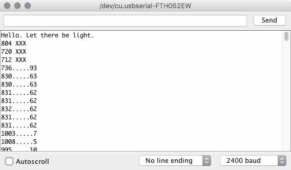
Like with the LCD, custom characters printed to the serial monitor use many precious bits. I found myself shortening those prompts as my sketch grew. I added a short delay (with flashing light) in the setup to give me time to swap out the ISP cable and attach the VCC and Ground to my phototransistor board. With an If...else conditional I setup a variable to adjust to the brightest light and subsequently calibrate the percentage conversion.
Next I tried making a sketch to work with the switch. I fished out my previous switch script and went to work.
#include <SoftwareSerial.h>
SoftwareSerial mySerial(0,1);         // RX PA1 12, TX PA0 13 (flipped)

// Using an ATTiny44
// Pin Configurations
const int switchPin = A3;             // PA3 10 ADC3
const int sensorPin = A2;             // PA2 11 ADC2
const int LED = A7;                   // PA7 6
const int timer = 125;
int sensorValue = 0;                  // variable to store the value coming from the sensor
int outputValue = 0;                  // variable to store the PWM
int countdown = 5;                    // set countdown equal to checks
const int checks = 5;
boolean lastSwitch = LOW;
boolean currentSwitch = LOW;


void setup() {
pinMode(LED, OUTPUT);               // declare the LED as an OUTPUT:
mySerial.begin(19200);              // I set this to 19200 and arduino monitor to 2400
mySerial.println("Illuminate me.");
}

boolean debounce(boolean last)
{
boolean current = digitalRead(switchPin);
if (last != current)
{
delay(5);
current = digitalRead(switchPin);
}
return current;
}

void loop() {
currentSwitch = debounce(lastSwitch); // press button to push five readings to serial.
if (lastSwitch == LOW && currentSwitch == HIGH)
{
mySerial.println("ok");
digitalWrite(LED, HIGH);             // delay to clear hand
delay(375);
digitalWrite(LED, LOW);
while(countdown < checks) {          // five checks
  countdown++;
  int sensorValue = analogRead(sensorPin);// read Phototransistor write to variable
  int outputValue = map(sensorValue, 0, 1023, 100, 0);
  mySerial.print(sensorValue);       // send reading to serial
  mySerial.print(".....");
  mySerial.println(outputValue);     // send percentage of total spectrum to serial
  delay(timer);
}
mySerial.println("done");
}
lastSwitch = currentSwitch;
countdown = 0;                          // reset while loop count
}
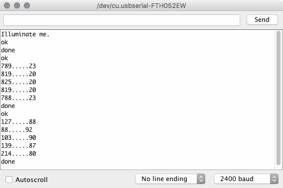
When you press the button, there is a brief delay with LED indicator for you to move your hand away from the phototransistor. Then five readings will be transmitted to the serial port. Rinse and await another button press.
The next step will be to add sensors and functionality for measuring voltage output, humidity and temperature (and possibly soil moisture because I found a sensor in the lab). Further, I need this information passively logged into a datasheet for analysis. I think I will start in on these tomorrow.
Download project files
I will post links to resources I have found helpful here.
Share this post...
« Previous post :: Phototransistor breakout board
In a previous project based on an ATtiny44 I added an expansion pin on PA2 (ADC2/AIN1/PCINT2). I think I can use that pin to take readings from a phototransistor; making this a nice little project to get generate some momentum. Remember: spiral development. First I examined Neil Gershenfeld's ATtiny45 schematic, the ATtiny45 datasheet, the ATtiny44 datasheet, andthe OP580DA phototransistor datasheet. Because both pins are compatible with Analog to Digital Conversion (ADC), the phototransistor should work with my ATtiny44 board. The first step is to design a board for the phototransistor, resistor, voltage, ground, and logic connections. I use Autodesk's Eagle....
Next post :: Bio-electro-chemistry »
The fabrication demands of this project are far less than other aspects. Keep it simple. Spiral develop. I essentially want an open-faced cube in acrylic. I will develop a grasshopper, parametric model with variables for overall dimensions, finger joint size, laser kerf, bolt and other holes (unrelated to box adhesion). The prototype is based on the work of Paolo Bombelli, et al. This is the desired composition. The pot, plastic fixture and possibly rubber washers will be laser cut and Jakob Skote's Moss Powered Wifi Jammer project. Excellent work. Visit them. Fast-forward a little in time and I have a...