Tags
Embedded programming
- Environmental monitoring with online data logging to Thingsv
- Grow monitors | What watches the watchers?
- LCD x Arduino
- Programming "Hello to the World" with C
- Breathing light : An arduino experiment
- Datasheet Atmel ATtiny24/44/84
- Echo : Programming.c
- Programming a programmer
- Arduino IDE, introduction
2017 Mar 20
#coding
#microCode
I am testing the assembly of the board by attempting to program it using C... for the first time.
Start by downloading the Makefile and the echo hello-world C program written by Neil Gershenfeld. To make things simpler, rename the *.make file to simple "Makefile". No extension. In MacOS the best way to do this is in the file information dialogue. Open the Makefile with a neutral editor, such as Textedit to learn about its setup. The first group of lines refer to the project name, the source of the project (echo hello-world C program), the Micro-controller (ATtiny44), and the clock cycles 20mHz. All matching the electronic components on my board. The second half refers to the two HEX files that will be generated. "avr-gcc" is a programming language compatible with ATtinies.
PROJECT=hello.ftdi.44.echo
SOURCES=$(PROJECT).c
MMCU=attiny44
F_CPU = 20000000

CFLAGS=-mmcu=$(MMCU) -Wall -Os -DF_CPU=$(F_CPU)

$(PROJECT).hex: $(PROJECT).out
avr-objcopy -O ihex $(PROJECT).out $(PROJECT).c.hex;\
avr-size --mcu=$(MMCU) --format=avr $(PROJECT).out

$(PROJECT).out: $(SOURCES)
avr-gcc $(CFLAGS) -I./ -o $(PROJECT).out $(SOURCES)
Several lines down in the file are the commands specific to my programmer: usbtiny.
program-usbtiny: $(PROJECT).hex
avrdude -p t44 -P usb -c usbtiny -U flash:w:$(PROJECT).c.hex

program-usbtiny-fuses: $(PROJECT).hex
avrdude -p t44 -P usb -c usbtiny -U lfuse:w:0x5E:m
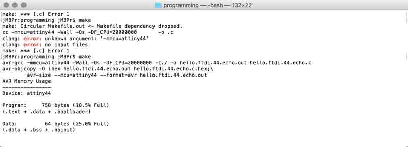
Open terminal. Browse to the folder with the two files and enter one simple command.
make
Initially, the command did not operate because the Makefile was corrupted by Textedit in my process of fiddling. I deleted the Makefile and downloaded another copy and the commanded executed.
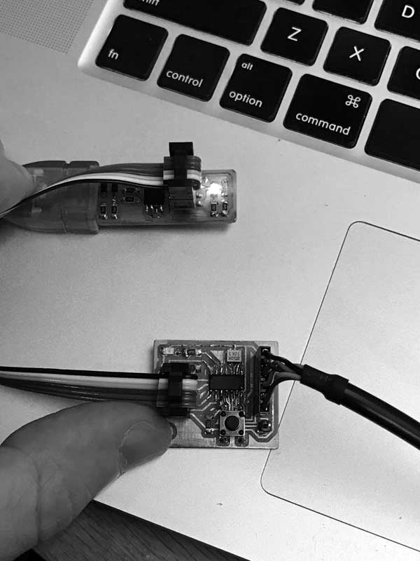
Now connect the boards to your computer. I connected the programmer I made previously to one USB port and the new board to my other via an FTDI to USB cable. The black wire aligns with the ground. Then with the grounds aligned (USB left), I can visualize how to properly connect my freshly fabbed ISP line.
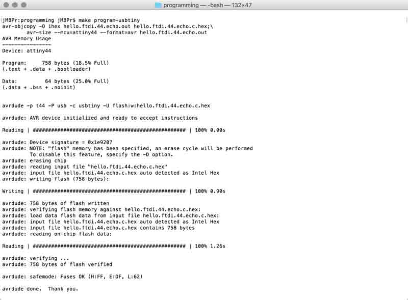
With the boards connected flash the program to the MCU:
make program-usbtiny
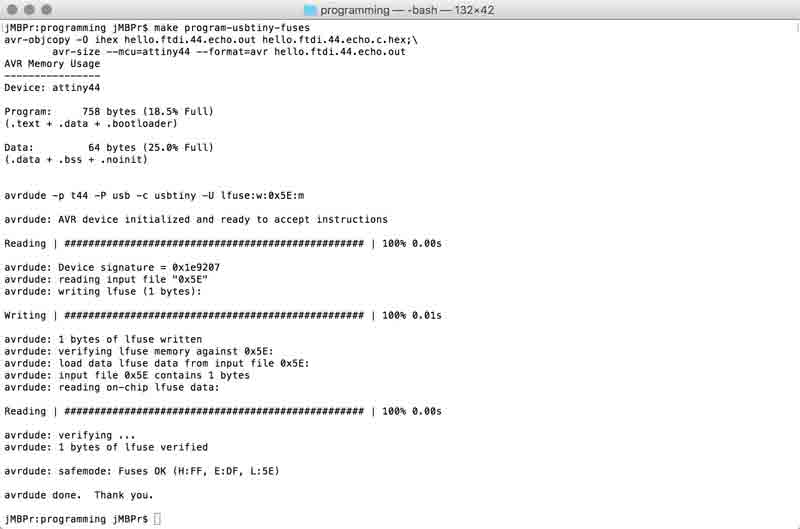
And set the configuration fuses:
make program-usbtiny-fuses
Now my board is recognized by my computer's USB drive. This next part was tricky because I did not know anything about serial monitors, much less python. Thankfully, where there are questions there is this. Ultimately, I was able to use Arduino and Python as serial monitors. I will explain both.
Python 2.7 is preloaded on MacOS yet needs to be extended with additional libraries for communicating with the serial port: Pyserial. Go there and download the appropriate installation files. Unzip. Direct terminal to the unzipped folder.
python setup.py install
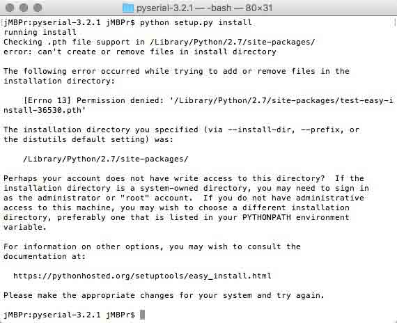
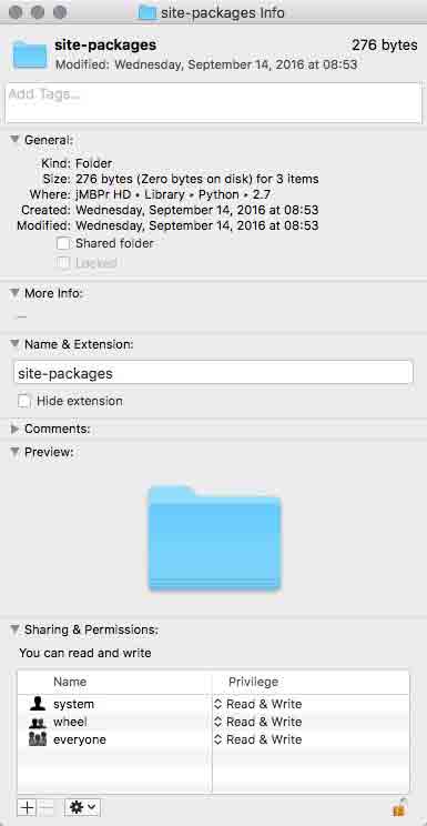
The Python folders on my computer were set to prevent me from making changes... MY COMPUTER! I took the shortcut of temporarily changing two folders' permissions:
/Library/Python/2.7/site-packages/
/usr/local/bin/
With that change, the installation was successful. Copy: rx.py and term.py into your working directory. With your board connected via FTDI, you need to find its serial port. Use a list command. /dev/tty stands for the "controlling terminal for the current process." Okay, well, I have to keep moving.
ls /dev/tty.*
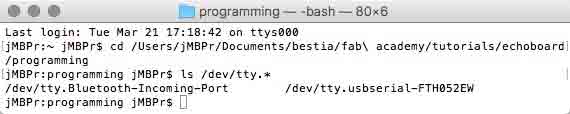
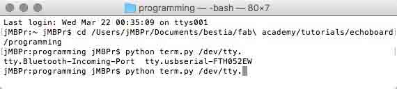
I am looking for the USB->FTDI cable. Fortunately, this is self-evident. Finally, you need to launch a python comm window with the programmed echo board. Issue a python command. Use term.py (which calls on a serial library installed previously). Point it at your FTDI connected device. Set the BAUD rate to 115200.
python term.py /dev/tty.usbserial-FTH052EW 115200
Another technique is to type up to the "...tty." then press TAB. A list of available serial ports will be listed. Copy/paste the correct one and end the command with the BAUD rate.
If all is correct, this window might open. Click somewhere in the window and press a key. You will not see any recognition of your key press within the window but your board should respond with the key you pressed. For some reason, I am receiving some odd inconsistencies: the name of the board is returned in variations, sometimes key cases are changed, and sometimes the space bar does not return a space. Also, when I try to quit the window, it stalls until I disconnect the FTDI cable. Still, it is mostly working.
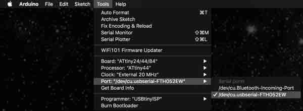
Alternatively, Arduino can be used as a serial monitor and it was a much easier setup. Ensure the Python serial monitor is disconnected (and vice versa) or it may cause problems for you. Browse to Tools>Port> and select your FTDI connection. Incidentally, this is a workable alternative to the ls terminal command. The address is slightly different but still operational. I know, I tested it.
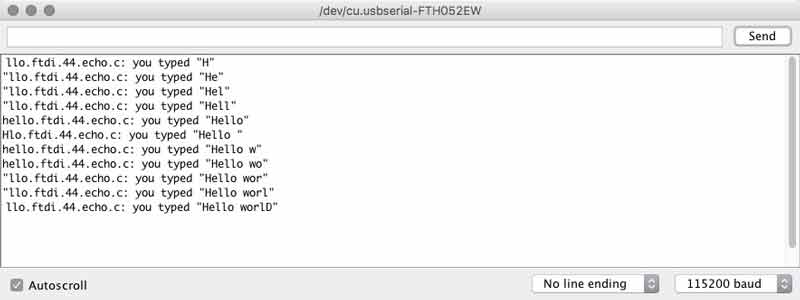
Return to the Tools menu and select "Serial Monitor". Type characters and press send. One at a time. Hello world.
I have found that garbled text sometimes is associated with mismatched BAUD rates so I tested this with different rates. The text became symbols.
I will post links to resources I have found helpful here.
Share this post...
« Previous post :: Testing constraint : machining materiality
With design intent sketched and prepared with assumptions digitally, I need to setup and execute tests of the machine and material. A three-axis CNC mill is similar to the tabletop CNC mill I used to cut PCBs. The endmill's orientation is locked perpindicular to the cutting surface and is moved along the length, width and height of the material. I am testing the bending of the material with a scored kerf and a through cut kerf with band thicknesses of 20, 30 and 40mm. And I have two types of custom joints with two thicknesses of band. The blue lines...
Next post :: Datasheet Atmel ATtiny24/44/84 »
Datasheets are hardcore product manuals for instructing makers on how to integrate specific products (ie electronic components) into systems. Datasheets are typically created by the product manufacturer and include technical and performative characteristics, connectivity information, coding examples, etc. A datasheet for an electronic component, such as an MCU like the ATtiny44, typically contains the following: Feature list and overview Pin configurations and descriptions Timing diagrams Reset and interrupt handling Register description Memories details Input/output informations Clock system Power management Packaging details and configurations and much more! This is the first time I have read a datasheet and I have only...