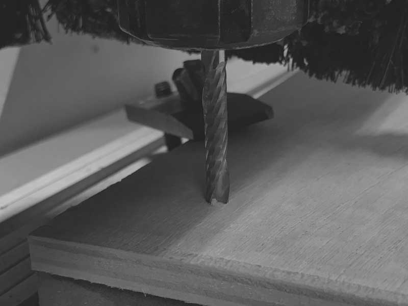
With design intent sketched and prepared with assumptions digitally, I need to setup and execute tests of the machine and material. A three-axis CNC mill is similar to the tabletop CNC mill I used to cut PCBs. The endmill's orientation is locked perpindicular to the cutting surface and is moved along the length, width and height of the material.
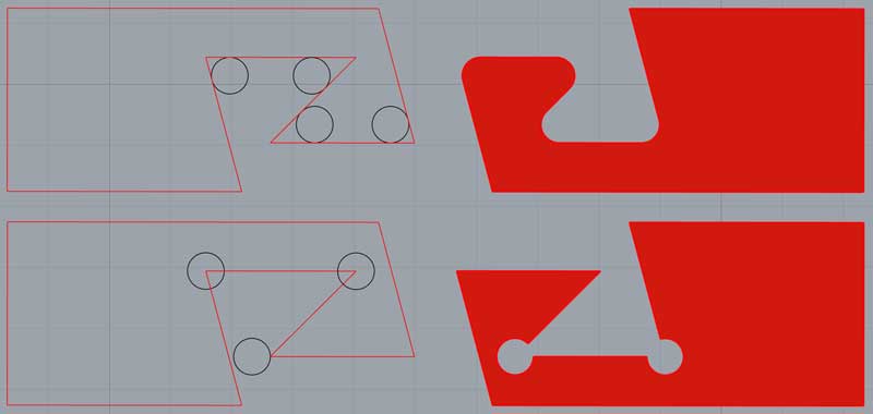
I am testing the bending of the material with a scored kerf and a through cut kerf with band thicknesses of 20, 30 and 40mm. And I have two types of custom joints with two thicknesses of band. The blue lines are scoring with a 3mm endmill and red cuts with a 6mm endmill.
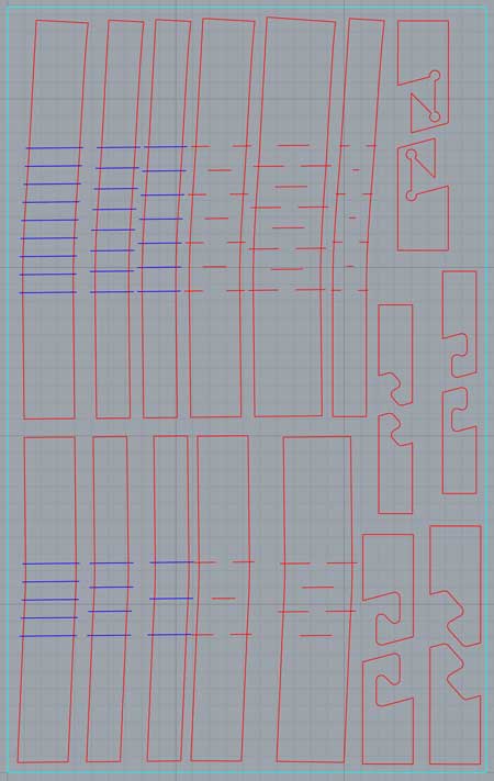
The cutting endmill is 6mm. This means any angle less than 180 degrees will have a 3mm radius fillet. Especially when designing connections, either draw with the fillet, or remove extra material behind the angles. Also, be mindful of the movement of the endmill. Any gap less than 6mm wide cannot be cut with a 6mm endmill. This is further dependent on the machine tolerances.
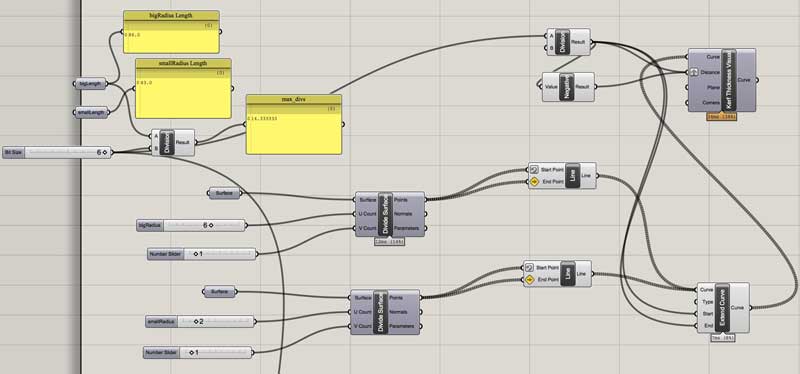
The kerf patterns are drawn with the intention that the mill is centered on the lines. Each space with a cut will be a flexible section of material while the spaces between the cuts will remain inflexible. To be considered is how deep the cuts, how segmented the bent appearance and how visible the grooves as they are bent, they widen. For quickly generating variations to be tested, I setup a simple grasshopper graph which additionally helped compensate for the slight directional changes that occur through the bending zones in this version of the overall design.
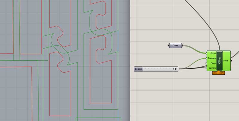
When organizing the pieces for cutting, tool path diameter needs to be accounted. I setup a simple grasshopper graph to help visualize this as I organized the pieces. And I varied distances between the pieces some to see how that would effect the machining. This is not exact. The tool will generally be moving between the green and red lines.
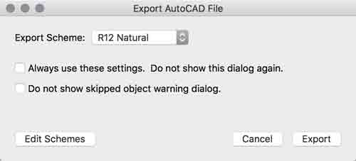
Now export the lines as an DXF for the CAM application. The Tongji shop requires me to use their CAM application, Type 3, which is inconvenient because it is Chinese language and can only be used by a lab assistant. After initially having file compatibility problems, I found exporting as an R12 Natural DXF from Rhinoceros works well.
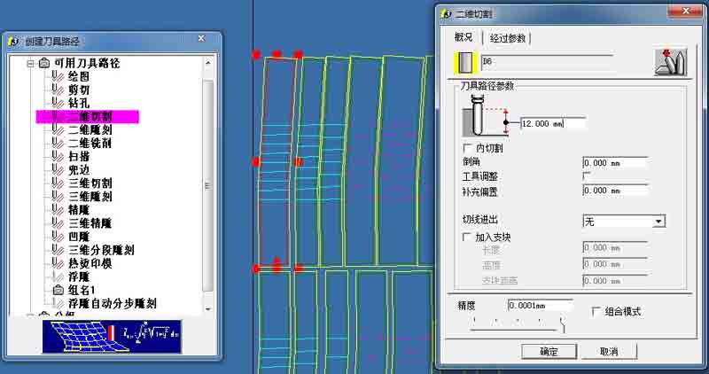
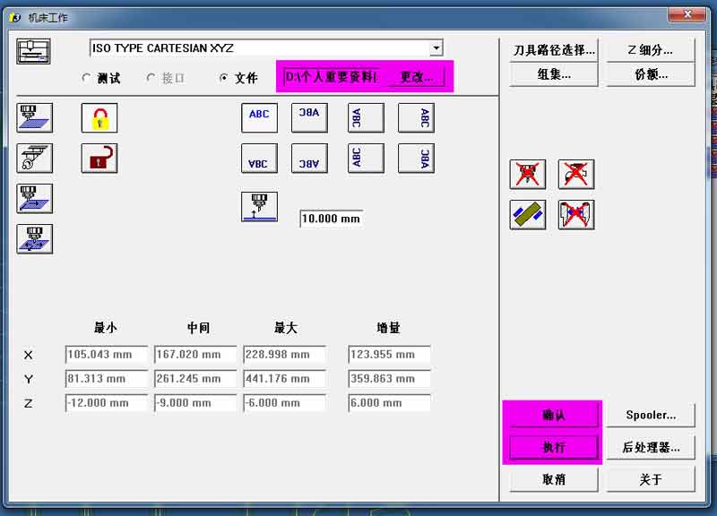
Open Type3. Import the DXF and start making the tool paths. This file will be separated into three jobs. One for the scored kerf, a second for the full cut kerf and finally the outlines. The ordering is critical for loading the machines into the mill and for minimizing movement of parts between cuts. First I created a file to cut the outlines. This dialogue sets the total material thickness, the 6mm endmill and the type of job: orientating the mill along the outside edge of the outlines.
This second tab sets the depth of each cut. 6mm for two passes.
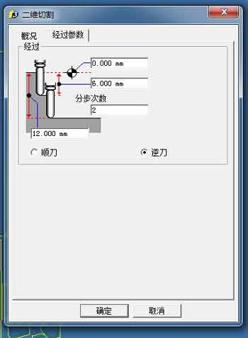
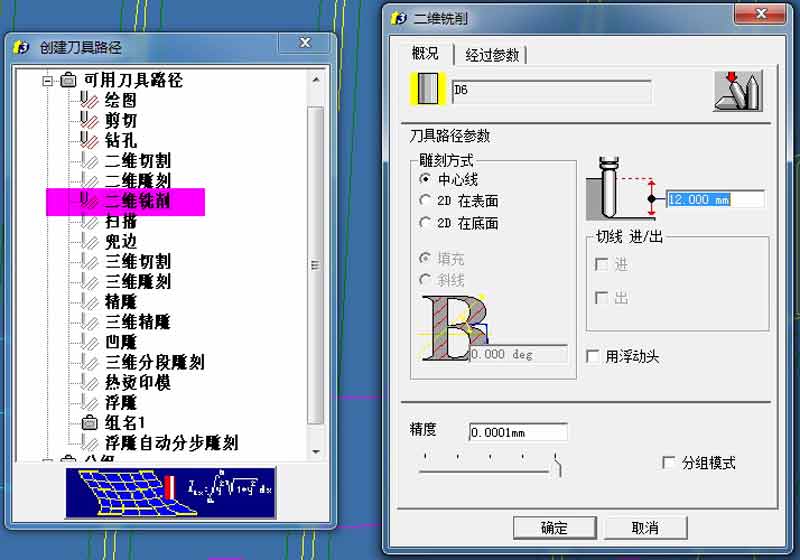
The other type of job requires the endmill to be centered on the lines. In the second tab the depth is set to 7.5mm for the score and 12mm for the full cut kerf.
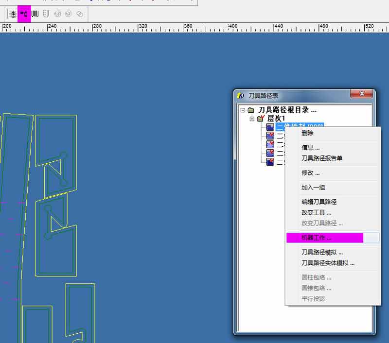
After the cuts are prepared, compile the code that dictates the movements to the mill. Select this option from the right click menu of each job. The lab technician was unable to show me how to make tabs in Type3. Tabs hold the pieces in place throughout the cutting and then are small enough to easily be removed with wood carving tools afterwards. I will attempt this job without tabs and that is a huge concern.
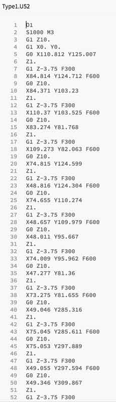
Set the file name in the top zone. Then press the bottom highlighted button first succeed by button in the middle. This generates the G code.
With a plugin, G code can be viewed in brackets, or other applications that will not impact the file type.
The mill is a Woodpecker, produced by a Chinese company in Shanghai.
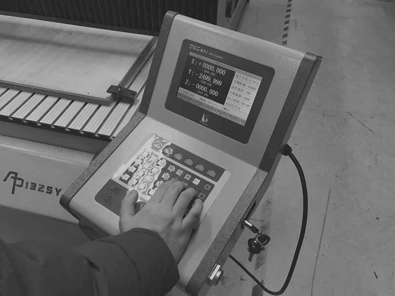
First I clamped the material to the mill and set the XYZ zero manually from the connected terminal. The Z is set to the top of the material surface.
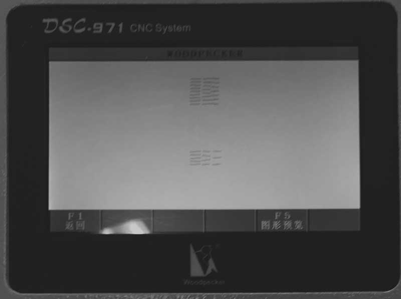
Straight away, in addition to the lack of tabs, I had concerns with the amount of bowing in the material and the fact it is not screwed into the safety substrate. True to form, this caused problems milling so in the future I will always screw the board to the substrate. When a file is loaded into the terminal, the toolpaths are visualized for confirmation.
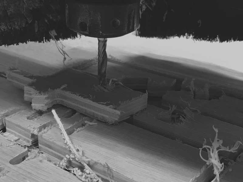
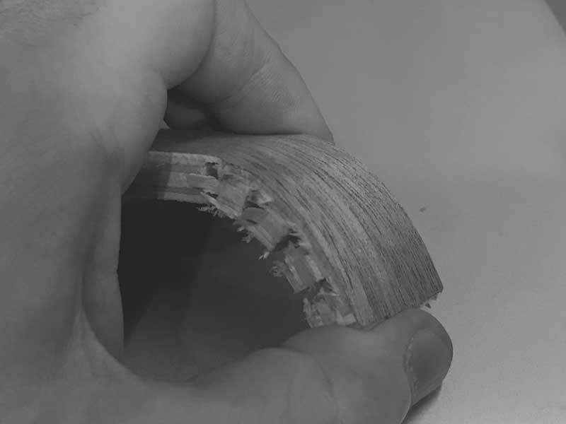
The first series of cuts are 7.5mm scores. Unfortunately, the fear of not screwing down the plywood immediately became a problem. Many of the scores went through the 10mm plywood. Further, the 6mm bit is too big for the size I need in the design. Visually, the cuts are too wide and in most of the resultant cuts the material simply broke when testing bending.
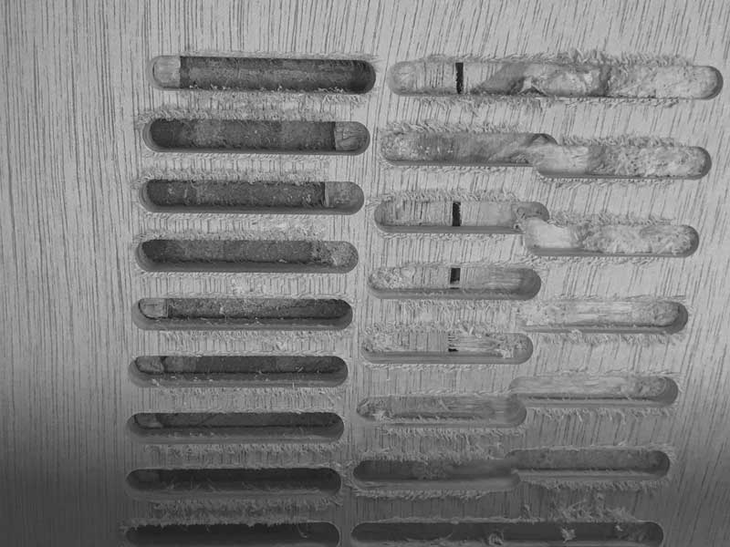
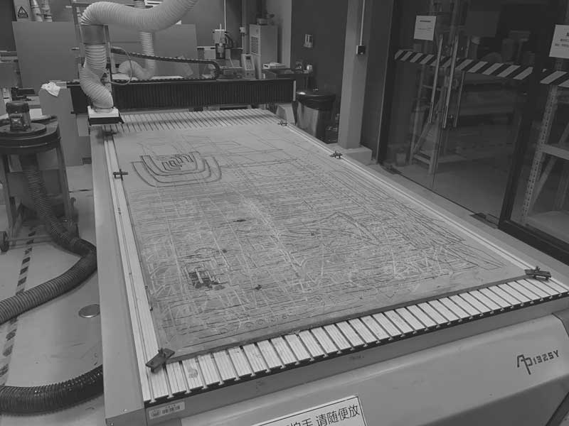
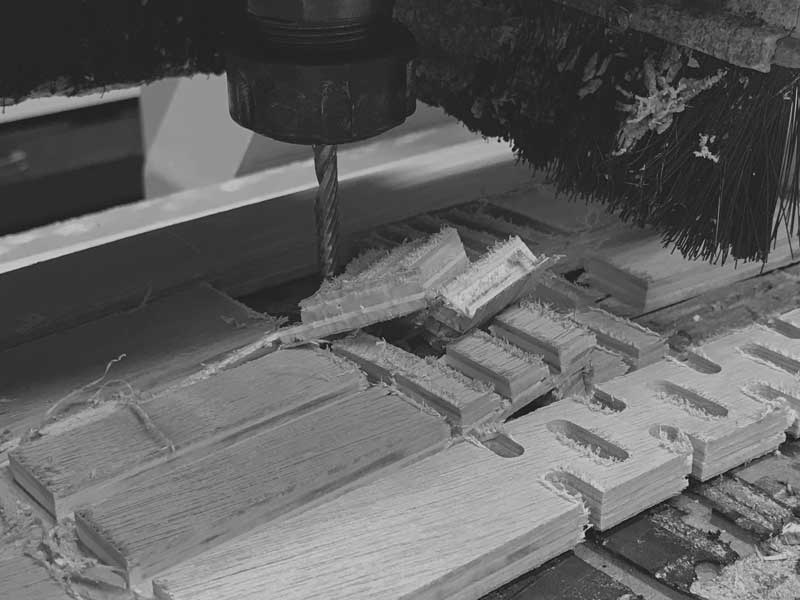
Next, along with the problem of the bowing in the plywood, the lack of tabs resulted in pieces flying around mid-job. No bueno, hombre. I cannot confidently say the tabs would have made a big difference on this particular job because the plywood was not screwed down. It is clear, though, that tabs are necessary. This is a language barrier that will need to be overcome before the next trial. Following are some brutal photos.
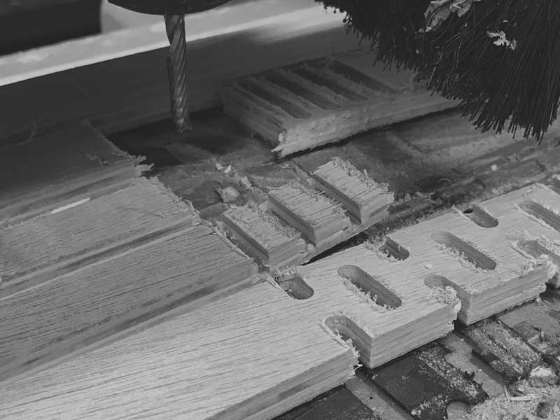
I kept the machine running because there were always unfinished parts that I hoped might be salvaged and it was so difficult just to get to the point of using the mill between schedule and language challenges. For the most part, well, as you can see, here is the whole bloody affair in one photo.
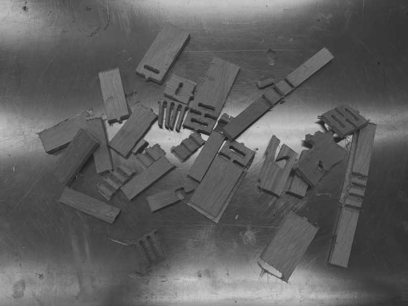
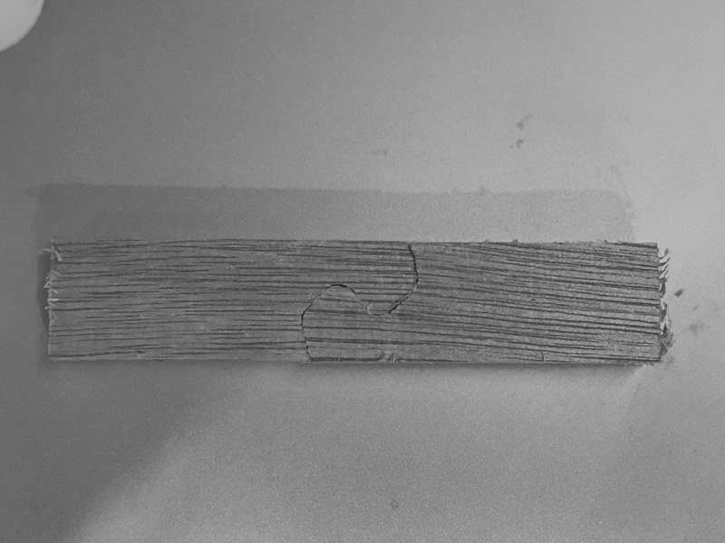
In the end I did get some effective joints and a piece of bendable kerf pattern. So along with improving the setup procedures, I do have some design feedback. I would like to try to gain access to a smaller endmill for the kerfing. I will widen the bands in the design and the joints could work as designed, but I will test some iteration.
This job is too tricky for the accessibility of this machine. I need to do loads of little experiments to get all the settings in place. I think this is a good start to an interesting little design, so I would like to see it through. I will follow Neil's advice in the review, laser cut a mockup first, find what can work and modify digitally, then test small pieces on the mill, modify digitally, and finally cut the first version on the mill. So, this is to be continued in another fab academy.
I will post links to resources I have found helpful here.
Share this post...
« Previous post :: Unravel : Mysteries, preparing a design to test 2-D milling
I wanted to make a work that appeared to be a single surface looped around and around like a coil or a spring. I like to make things that use machines natural ease in replication as a starting point and then find ways to create variation or intrigue. It could be imagined that this one thing can be unwound into a long straight line or that this coiled state is the natural tendancy of the material. One important note: in this first prototype I plan to use machine kerf to make the plywood flexible in specific zones. In future iterations...
Next post :: Echo : Programming.c »
I am testing the assembly of the board by attempting to program it using C... for the first time. Start by downloading the Makefile and the echo hello-world C program written by Neil Gershenfeld. To make things simpler, rename the *.make file to simple "Makefile". No extension. In MacOS the best way to do this is in the file information dialogue. Open the Makefile with a neutral editor, such as Textedit to learn about its setup. The first group of lines refer to the project name, the source of the project (echo hello-world C program), the Micro-controller (ATtiny44), and the...