2017 Mar 14
#model3d
#cut2d
#CAD
I wanted to make a work that appeared to be a single surface looped around and around like a coil or a spring. I like to make things that use machines natural ease in replication as a starting point and then find ways to create variation or intrigue. It could be imagined that this one thing can be unwound into a long straight line or that this coiled state is the natural tendancy of the material.
One important note: in this first prototype I plan to use machine kerf to make the plywood flexible in specific zones. In future iterations of this project or similar designs, I would like to explore bending, for instance with steam, and/ or finishing to conceal the intentional kerf.
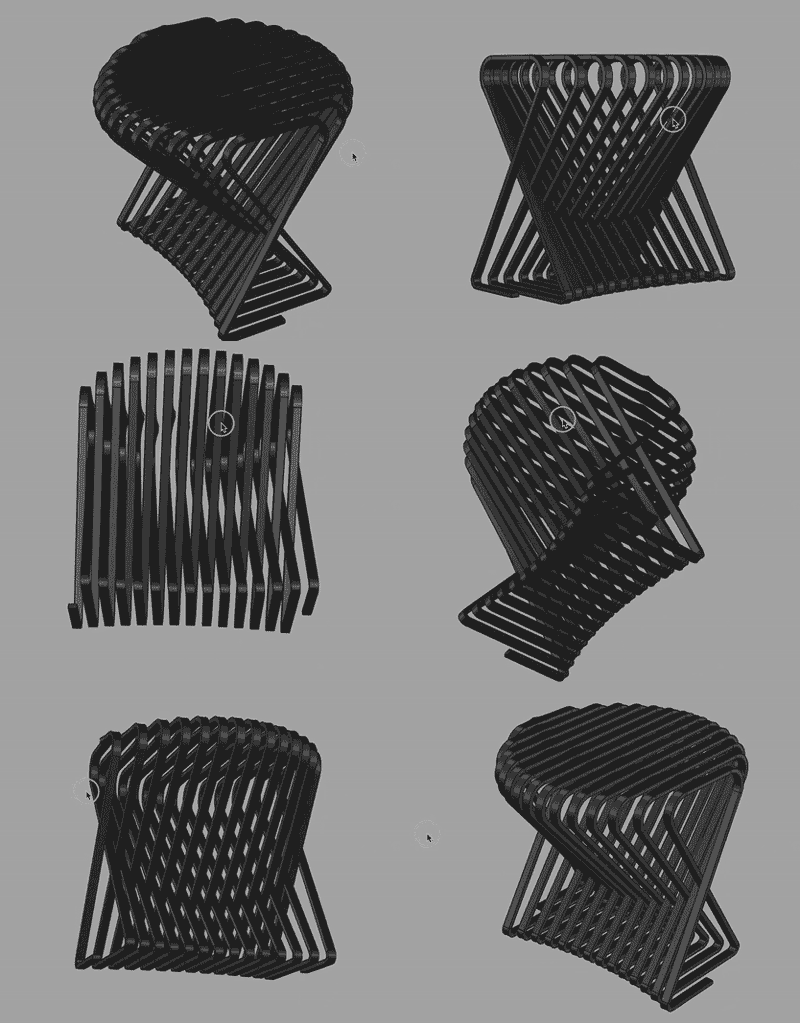
I started using a combination of Maya, Rhinoceros and Grasshopper. I hope to have time after my first built prototype to convert the entire model into a grasshopper definition for versioning. For me, it is yet difficult to start a design in grasshopper. I like to design more like sculpting: adding material, tearing material away, fast, intuitive and sloppy, which is easy in Maya and once I have a clearer version of the design, I can begin translating the variables into Grasshopper and create a generative model. Nonetheless, Maya does propogate several changes throughout its history. As I starting point, I intend to use 10mm thick plywood and the overall dimensions fit within a 600mm x 600mm x 600mm virtual box. That may change with material testing. The ribbon is typically 20mm wide.
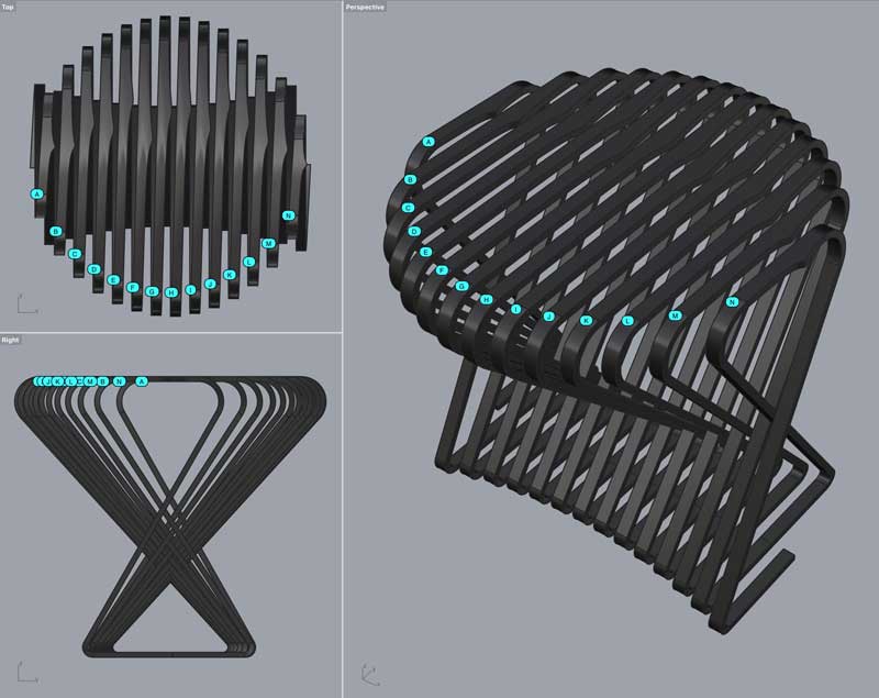
The bending areas will be living hinges from tool kerf. I need to test what the best pattern for this will be and optimize the radii. I think I prefer just a simple straight line cut through the top few layers of plywood which research suggests work in both directions. That is good, because the bends are reversed from top to bottom. Thr project will look cleaner with the cuts facing inward which could be achieved by flipping the material between cuts. Flipping the material is a complication I will reserve for a later version. Otheriwse, the kerf will need to cut through the thickness of the material and the bands at 20mm may be too thin.
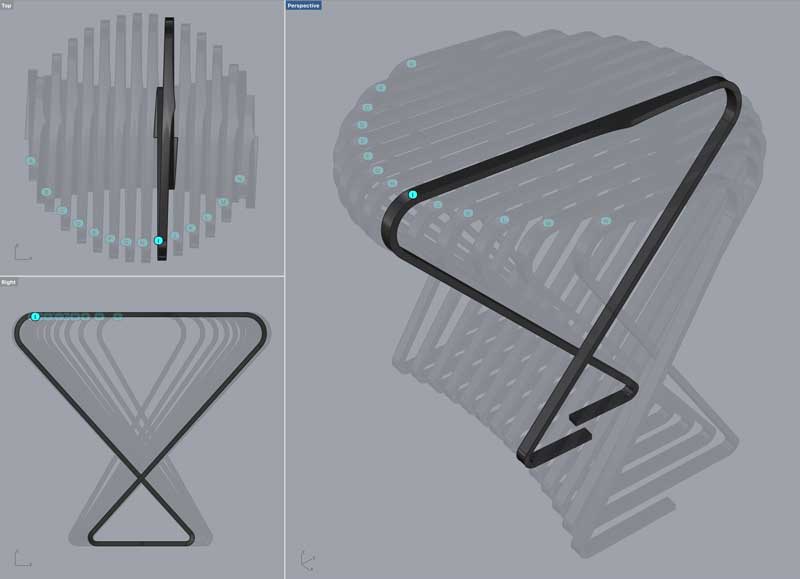
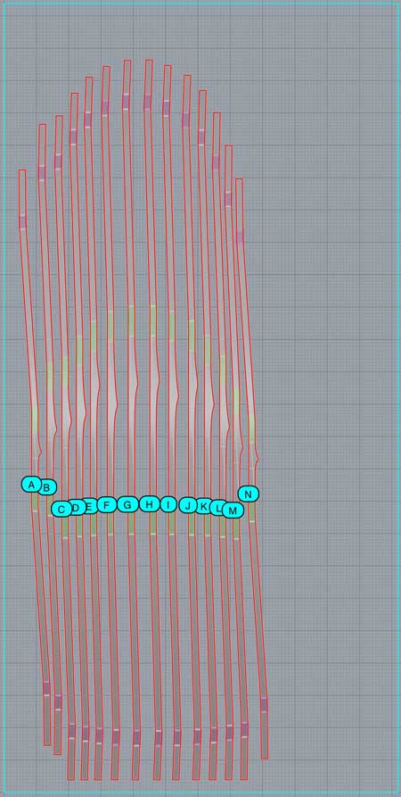
Fourteen bands are broken out of the one continuous band in the digital model. Material constraints primarily dictate this decision. I could reduce the number of bands if the joints were not aligned which may be interesting if not for the structural challenges of putting joints anywhere but the bottom where there is the least amount of vertical momentum. I think for the first version, there are enough challenges withstanding. Thus, the joints will be in the center of the base.
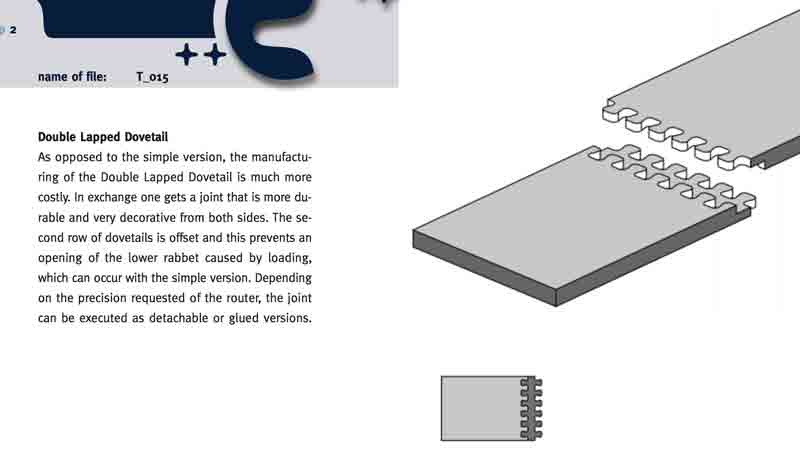
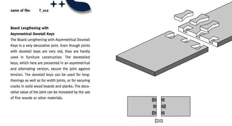
A benefit to flipping the material between cuts is the possibility of making a lapped dovetail joint which I think would be stronger. As I am not flipping the material between cuts, I will do a start with a variation of dovetail cut through.
This drawing is for reference. It shows the current size of the cuts relative to the stock. The kerf patterns need to be optimized in testing and then I will likely extend the cuts beyond the red lines (full cuts). Plus, the joint needs to be added to the ends after testing. Then I can optimize the positioning to save material. No reason to do that effort before finalizing the cut shapes. The purple zones are 20mm radius bends and the green 40mm. The darkest lines of the grid are spaced 100mm.
I will post links to resources I have found helpful here.
Share this post...
« Previous post :: Precedents
Most of the science I used comes from Dr. Paolo Bombelli's excellent research in the field of bioelectrochemical processes. This includes his published research: Electrical output of bryophyte microbial fuel cell systems is sufficient to power a radio or an environmental sensor and Biophotovoltaics: oxygenic photosynthetic organisms in the world of bioelectrochemical systems and Biophotovoltaics: Energy from Algae published in Catalyst Vol 21 #4, April 2011. Alex Driver and Carlos Peralta's collaboration with Dr. Bombelli Moss Table. In a series of collaborations, they were able to run environmental sensors and a small LCD display for two weeks uninterrupted and operate...
Next post :: Testing constraint : machining materiality »
With design intent sketched and prepared with assumptions digitally, I need to setup and execute tests of the machine and material. A three-axis CNC mill is similar to the tabletop CNC mill I used to cut PCBs. The endmill's orientation is locked perpindicular to the cutting surface and is moved along the length, width and height of the material. I am testing the bending of the material with a scored kerf and a through cut kerf with band thicknesses of 20, 30 and 40mm. And I have two types of custom joints with two thicknesses of band. The blue lines...