2017 Feb 15
#model3d
#coding
#wildCardboard
#CAD
I decided to try learning the Rhinoceros parametric GUI plugin Grasshopper for the cutting prototype. The Grasshopper project's aim is to make programming easier to understand through an intuitive visualization. The GUI looks similar to Antimony with a model window and a graph window. Scripting nodes in Python, C#.net and VB.net is also possible. Grasshopper is available with Rhinoceros on MacOS and Windows. Launch Rhinoceros. Enter "grasshopper" in the command line. The Grasshopper interface will launch. Across the top are several tabs which contain links to "objects" which are scripts of varying complexity.
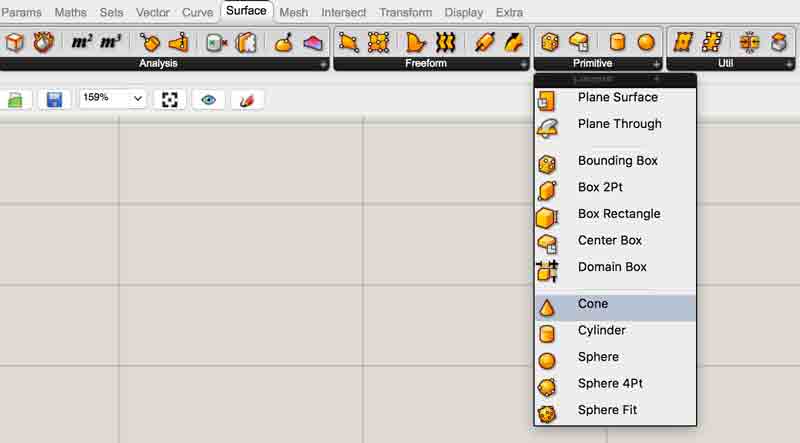
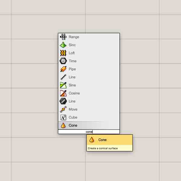
The primary section of the screen is the graph area. Screen navigation mirrors Rhinoceros. Double clicking in the graph area launches a command box, a similar utility to Rhinoceros' command line. Begin typing in a desired command and a list of selectable similar tools will appear.
Selecting an object from the command line or the tabs will drop it into the graph. The objects inherent stuff from other objects via linking or from assigned things existing in the rhinoceros window, i.e. a point. As the objects are linked together, they make things. This is when the fun happens. Keep in mind, this is not a linear form of modeling. Anything can be changed at any point anywhere within the graph and those changes are instantly propogated throughout the graph.
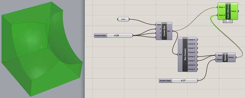
Because there are loads of great tutorials online, I will not explain much of the basics. Although, to ensure a baseline understanding of the interface and function, I created this delightful little graph. I think I have seen Professor Gershenfeld make a few of these... A cube is generated on a center point. A pair of cloned spheres are centered on two of the cubes corner points. And ZAP! POW! ZINGER! The spheres are subtracted from the cube. The left most number slider controls the lengths of the cubes segments. The other slider dictates the radius of the spheres. The point object is referencing a point created in Rhinoceros' model space (select the model space thing, right click on the grasshopper object, set one point) If that point moves in model space, this cube thing moves with it. Also, notice that one node can control multiple inputs just as multiple outputs can control a single input. Connect inputs/outputs by dragging a curve from one nipple to the other.
The dark gray objects are hidden from view in the model window. If I were to show these, we would see the original cube and spheres and the cube corner vertices. As the grasshopper graph fills, following the work in model space can be difficult without adjusting the visual properties of the grasshopper objects. You can show/hide by selecting the object and pressing space bar.
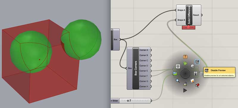
Finally, from the same menu, selecting the egg icon "bakes" that node. In other words, the grasshopper object will be permanently imported into the Rhinoceros model space. However, changes in the graph will no longer be applied to that object (the grasshopper node will continue to propogate changes and can be baked any number of times throughout your development process). This is useful when something is ready to export from Rhinoceros, such as for rapid prototyping.
There are plenty of free tutorials online. I more or less randomly chose this series. Linked here is the first of fourteen. The online community is strong and googling questions typically yields quick answers. If the information I posted here is not enough to get started, I suggest using as little time as possible with a tutorial before diving into your own creation. I find it much more fulfilling to learn as you create your own thing.
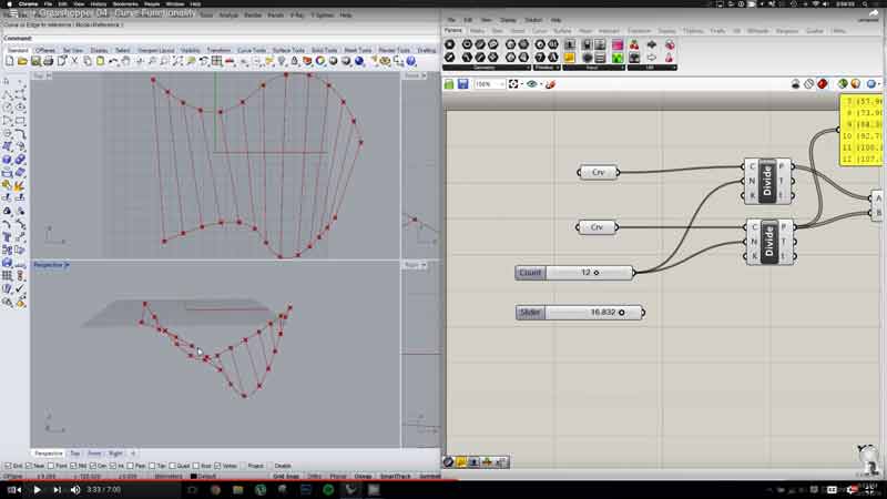
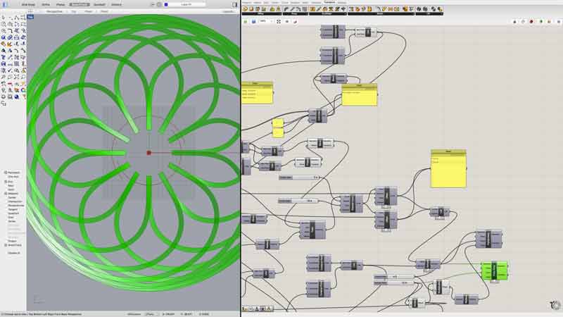
Here are a couple screenshots from the tutorials. Prepare for that graph to get exponentially more complicated...
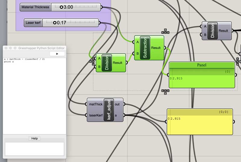
This is an example of the scripting interface. It appears writing on MacOS is as of yet more laborious than Windows because the language does not provide any hints, ala brackets. Python has many syntaxes along with custom Rhinoceros syntaxes and this is where without hints I am thus far lost. Well, that and the fact I wrote my first python script a few days ago.
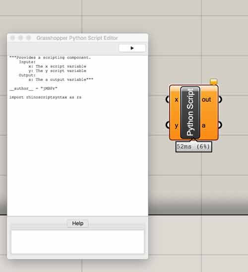
I certainly will use scripting in the future to simplify my Grasshopper graphs. This is a simple example of combining two objects into one Python object. The green Division and Subtraction objects are written into a simple formula which handles both operations in the Python object. Now two nodes are replaced by one.
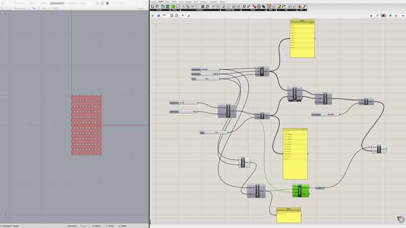
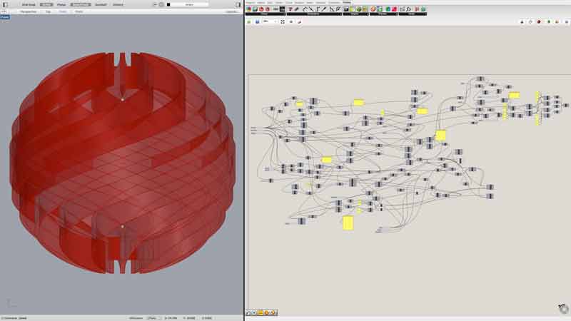
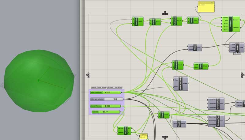
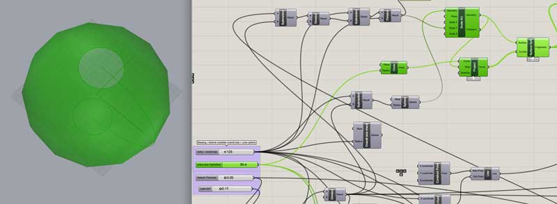
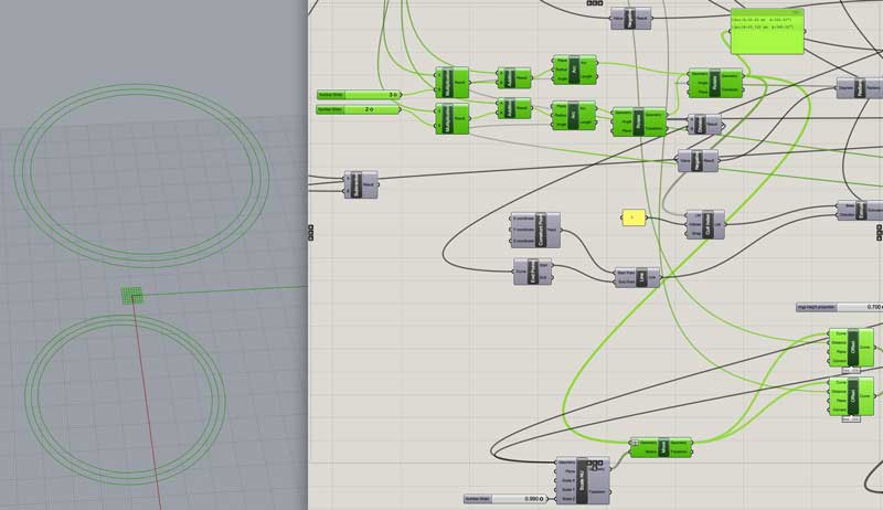
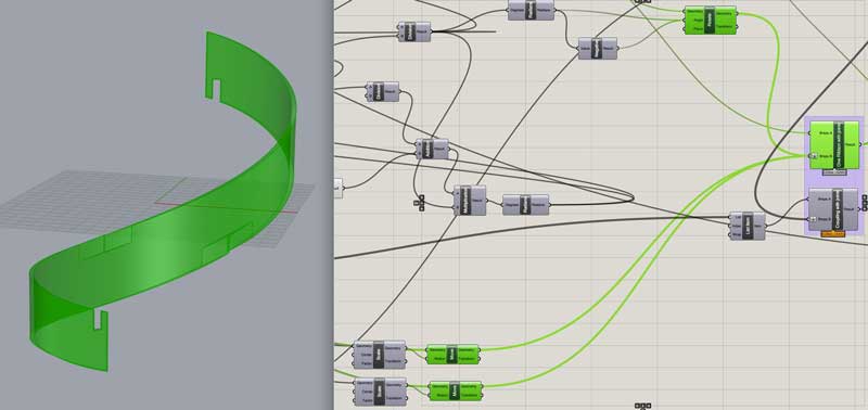
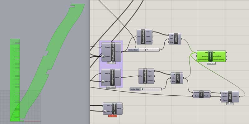
Now, let us skip closer to the end and then try to work back. This is how my nearly finished graph looked. Side note, I highly recommend live blogging your work, otherwise, like me and this project, you will essentially be doing it twice in decoding the effort.
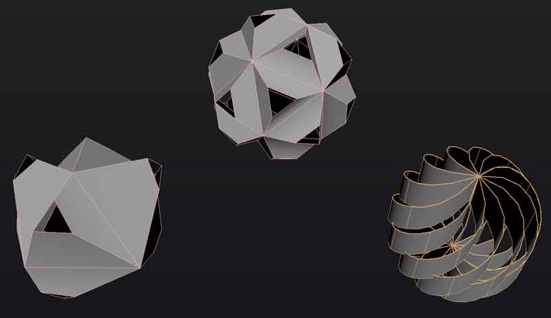
I began with some sketches in Maya to generate quick ideas. I can sketch in 3D modeling space almost as quickly, yet way more effectively, than I can on paper. In 3D, I get tons of additional information beyond a sketchbook sketch. I was thinking of things with volume. The spiral idea looked difficult because it involves one directional bending, tricky joint angles and it would probably be much more difficult to model (find the 3 dimensional rotation angles of the modified octahedron / icosahedron, array) . So I selected the spiral thing for further investigation. Why not?
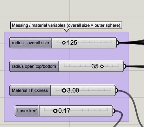
I start by considering seven basic design variables: Overall size, the size of the opening at the top and bottom, material thickness, laser kerf (related to material type), number of ribbons, the ribbon sweep, and the ribbon height.
top/bottom opening size : Radius of the top and bottom openings (opening measured from ends of ribbons, not ring structure)
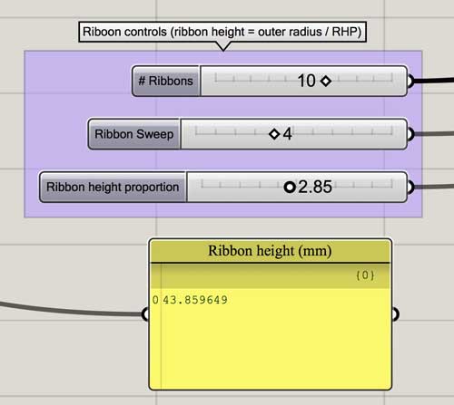
ribbon height proportion : This variable is admittedly strange. Ribbon height should have been automatically set as a relationship between the number of ribbons and the sweep angle and this could have been a flex multiplier from that basepoint. I never built that in though, so this number simply operates as a divisor for the overall radius variable. I recommend using the slider visually to ensure the ribbons intersect on the top and bottom for the midway connection which is critical.
number of ribbons : Total number of ribbons.
ribbon sweep : Total angle a ribbon sweeps in its journey from the top to the bottom. This number represents how many ribbon starting points the end point moves clockwise. (ex. 360/10x4=134 sweep angle). The variable is set as an integer in this manner to ensure the top and bottom connections align and because... math.
material thickness : The thickness of the material to be used for the thing.
laser kerf : Optional setting (if no need, set to zero). Optimize laser cutter settings for the material, measure kerf and enter here for higher precision in the joints.
Following are the objectives of the grasshopper graph.
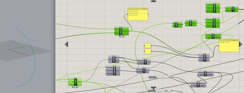
Create a reference sphere for the overall shape.
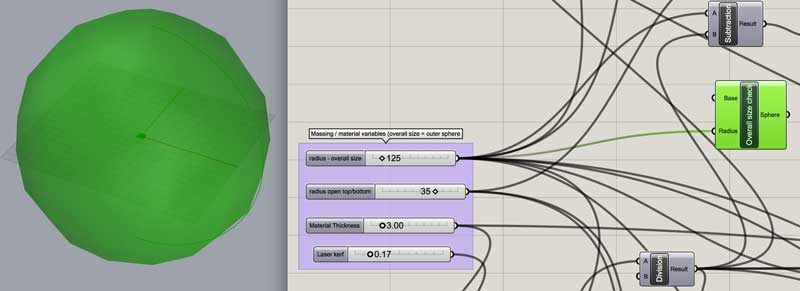
Adjust the size of the sphere according to the user variables to compensate for the vertical thickness of the ribbons. If the ribbons are extruded based on a sphere, the result will be an oval object.
Trim a variable dependant circle from the top and bottom of the sphere.
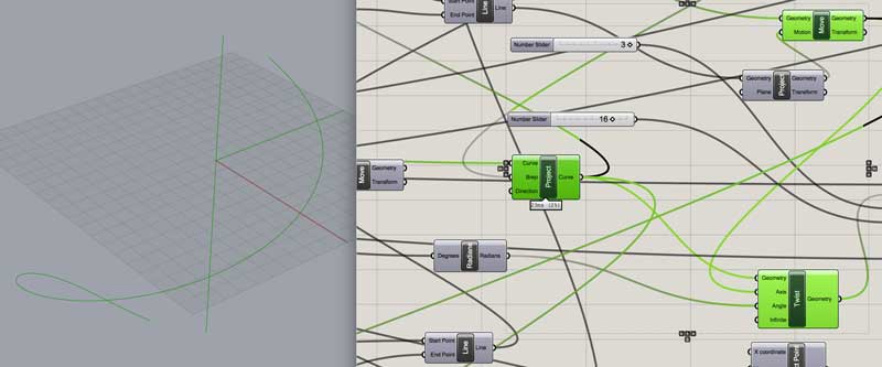
Project a line onto the trimmed sphere to create the path for the ribbon.
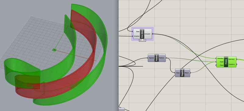
Twist the projected line a set angle based on a multiplier of 360 degrees divided by the number of ribbons variable. This way the top and bottom of the ribbon origins align.(Grasshopper operates in radians for which there is a simple conversion object for changing degrees into radians.)
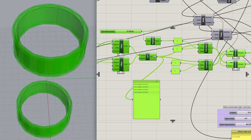
Offset the twisted line in each direction half of the material thickness optionally accounted for laser kerf. Then Extrude the two lines to the desired height and connect all edges into a solid.
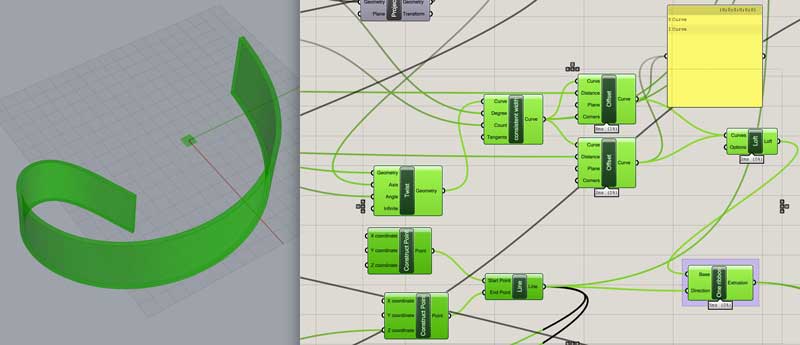
Offset the circles from number 3 a multiplier of material thickness (for the ribbon overrun) and two additional material thickness to generate three curves for the top and bottom couplings. (I redrew these circles as arcs so they could be unrolled and more accurately reflected the materiality of the finish product. I could also visualize the ends of the surfaces.)
Extrude the paths the desired height of the couplings and connect all edges into a closed surface. In this case, 70% the height of the ribbons.
Difference the joints from the ribbon. This is two parts: the couplings and the mid-section, adjacent ribbons. First, move a copy of each pair of couplings half a thickness towards the center of the original sphere (0, 0, 0).
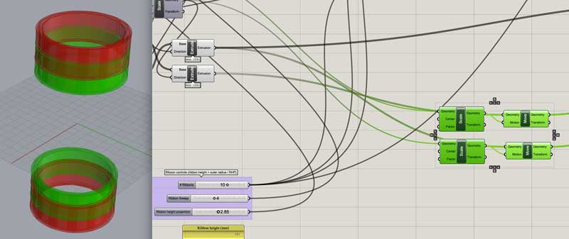
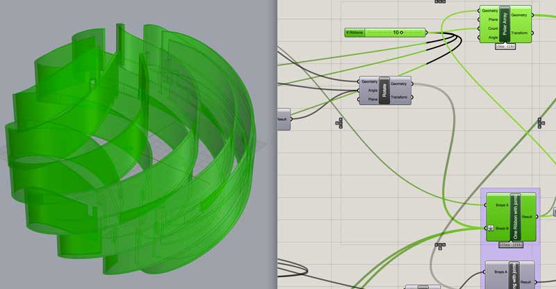
Rotate a copy of the ribbon in either direction 360 degrees / number of ribbons.
Difference the reultant 6 objects from the ribbon. Now we have the joints for the ribbon piece.
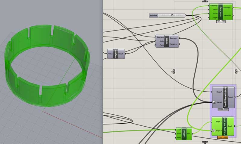
Polar array the jointed ribbon: 360 degrees / number of ribbons.
From an inside coupling (which shares its outer surface with the outside coupling), top or bottom, difference the arrayed jointed ribbons. Now we have all the pieces locked together proportionally and jointing automatically. All the couplings could be differenced from the array for visuals.
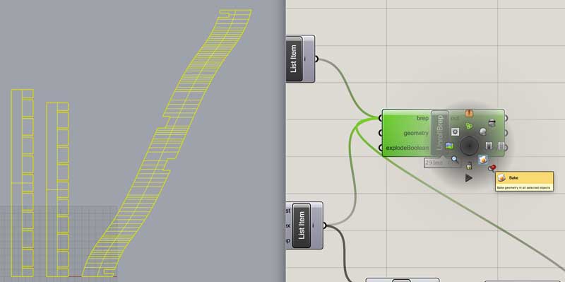
From one of the inside couplings (top or bottom) and the original ribbon, explode these polysurfaces and use the index to reduce the ribbon to the inside face and the inside and outside face of the coupling. Due to what I assume may be some tolerance issues, the intersections on one of the surfaces showed errors. I offset the good surface the material thickness to replace it.
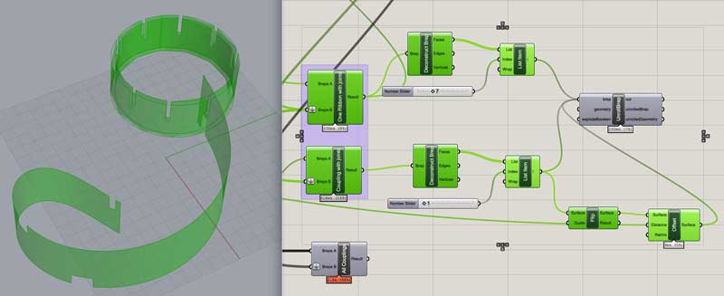
Unroll these three faces. (I found the unroll surfaces object here. Users can generate and share Grasshopper objects.) In the image, all the objects are pinned to the model origin. Thus the two coupling patterns are aligned.
Bake.
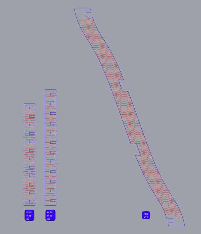
Quick review: three components are required for the build. Two components, nearly identical, are installed parallel and make up the coupling at the top and bottom. Regardless of the variables, these always come in two pairs. The open ends of the couplings are rotated 180 degrees so the combination will hold as a circle when connected to the ribbons. The number of ribbons is variable based on preference, overall size, and sweep. The notches at either end lock into the couplings. The notches in the center grab the next ribbon in the seqence at the center of the thing. This is necessary to counter the twisting torque. Check out Wild Cardboard for the build.
Future objectives for parametrics:
- apply the kerf bending pattern in relation to intended surface curvature and component edges
- generate user-defined joint types at the grasshopper cut joints
- populate a user-defined laser bed as tightly as possible, or restricted to certain preferences such as alignment to material grain or spacing
I will post links to resources I have found helpful here.
- Grasshopper Tutorials : Some tutorials I ran through on youtube.
- Unroll surfaces : Grasshopper object for unrolling surfaces.
- Python Scripting in Grasshopper : Helpful 5 part introductory series.
Share this post...
« Previous post :: Kerf : what is it? why is it? why care?
A laser beam is generated in the back of the machine and reflected through a series of mirrors, through a focusing lens then the material. The narrowest part of the beam, around an 0.32mm diameter, is aligned to the material (z-axis). The head of the machine moves along X and Y axes across a cutting bed directing the laser through the designated cuts. The intensity, speed, and pulses per inch (ppi) are user defined variables, in my case defined first by line color in the design software and second via a dialogue in the machine settings. These variables will effect...
Next post :: Vinyl cutting, introduction »
To test the vinyl cutter, I prepared a bēstia logo in Adobe Illustrator. I converted the graphic into a composition of vector shapes using the live paint tool. Now: cut time. First load the material into the machine. Release the clamp in the back. Align the sheet to the far left, parallel to one of the vertical lines along the front of the machine, and position the wheels to the furthest edges of the paper within the white marked zones. Return the clamp lever to the pressed position and notify the machine material is loaded. In this case, I used...