Tags
#coding
#electronics
#pureImagination
#microCode
Pure Imagination
- Environmental monitoring with online data logging to Thingsv
- Inventory
- Hessian/ burlap/ crocus composites
- CNC milled wood frame
- Grow monitors | What watches the watchers?
- Grow module | Design and fabrication
- Grow Module | The science
- Processing Light Graph
- Milling a composite mold
- Composites : Modular growth, testing
- Bio-electro-chemistry
- Bioelectrochemical testing pod
- LCD x Arduino
- Precedents
- Discussion
- Design, Materials and Methods
- History : Early concepts
2017 Apr 06
#coding
#electronics
#pureImagination
#microCode
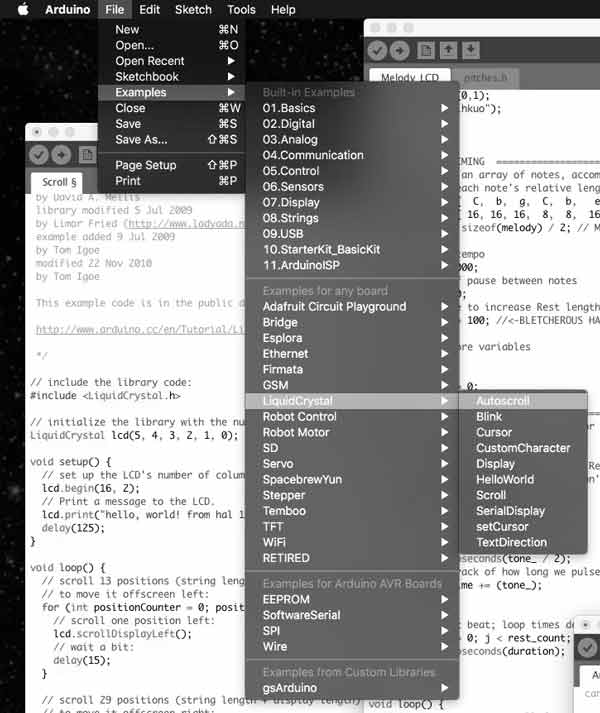
Arduino has a built in libary, "LiquidCrystal.h", for programming this type of LCD. I thought it would be fun to imagine a prototype of HAL 9000 prior to artificial intelligence using the LCD display to communicate and the LED to hint life.
Arduino IDE is packaged with many sketches of LCD functions. Browse to File > Examples > LiquidCrystal and you can check those out.
First, write in the sketch the command to send the library for the LCD.
#include <LiquidCrystal.h>
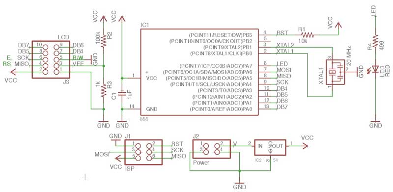
Then, you need to dictate which MCU pins are connected to the RS, E, DB4-7 pins of the LCD (in that order). That information can be found by taking a look back at the board schematic and the ATtiny -> Arduino pinout diagram.

Write the code in the Arduino sketch as such, replacing the pin types with the pin numbers. The first box is the proper sequence, the second is the correct code for my board.
LiquidCrystal lcd(RS, E, DB4, DB5, DB6, DB7);
LiquidCrystal lcd(5, 4, 3, 2, 1, 0);
After examining and loading the examples to my board I made this modification of my breathing sketch and added some "dialogue" for HAL 900. I find that sending characters like this to the LCD, quickly exhausts the available programming memory. I think each character averages 1 byte of dynamic memory (maximum 256 bytes).
#include <LiquidCrystal.h>

LiquidCrystal lcd(5, 4, 3, 2, 1, 0);

const int ledPin = 7;
int ledLevel = 255;
int timer = 30;
int ledChange = 15;
int ledMax = 255;
int ledMin = 0;
int ledPace = 5;


void setup() {
//LCD stuff
lcd.begin(16, 2);
lcd.setCursor(0,1);
lcd.print("HAL 900");
//LED stuff
pinMode(ledPin, OUTPUT);
ledMin = ledMax - (ledChange*(ledPace*2));
ledLevel = ledMax - (ledChange*ledPace);
}

void heartOne() {
while(ledLevel < ledMax) {
ledLevel = ledLevel + ledChange;
analogWrite(ledPin, ledLevel);
delay(timer);
}
while(ledLevel > (ledMin + (ledChange*ledPace))) {
ledLevel = ledLevel - ledChange;
analogWrite(ledPin, ledLevel);
delay(timer);
}
}

void heartTwo() {
while(ledLevel > ledMin) {
ledLevel = ledLevel - ledChange;
analogWrite(ledPin, ledLevel);
delay(timer);
}
while(ledLevel < (ledMax - (ledChange*ledPace))) {
ledLevel = ledLevel + ledChange;
analogWrite(ledPin, ledLevel);
delay(timer);
}
}

void loop() {
heartTwo();
heartOne();

lcd.clear();
lcd.setCursor(0,0);
lcd.print("/"I am putting");
lcd.setCursor(0,1);
lcd.print("myself to the...");

heartTwo();

lcd.clear();
lcd.setCursor(0,0);
lcd.print("fullest possible");
lcd.setCursor(0,1);
lcd.print("use, which is...");

heartOne();

lcd.clear();
lcd.setCursor(0,0);
lcd.print("all I think that");
lcd.setCursor(0,1);
lcd.print("any conscious...");

heartTwo();

lcd.clear();
lcd.setCursor(0,0);
lcd.print("entity can ever");
lcd.setCursor(0,1);
lcd.print("hope to do.\"");

heartOne();

lcd.clear();
lcd.setCursor(0,1);
lcd.print("HAL 900");
}
You can download your own copy of the sketch there.
Download project files
I will post links to resources I have found helpful here.
Share this post...
« Previous post :: LCD ATTiny44 PCB
I am using a Lumex 16*2 character LCD Module. This LCD only requires 5v and six data pins to get up and running. I do not have a PCB with the free pins or proper configuration to use with this LCD. Not a problem however, because I have learned my way around designing, milling and stuffing PCBs. Get it. I started by inspecting Neil Gershenfeld's example LCD board. I posted a low resolution copy of the image here for convenient reference. The linked version is better. While following this is great for a beginner like me, I quickly became aware...
Next post :: Fabricating, wiring, learning »
This dance is as follows: mill, solder, wire. Familiar aesthetic for the board. Milling the traces at 0.10mm depth once again was unsuccessful so I dropped the depth to 0.15mm and milled on top of the previously milled stock. Soldering was significantly faster. This time, when heating the connections I kept a count in my head which varied from an one to three count according to the size of the components. Worked well in terms of pace. Checked all the connections with a multimeter. No problems. Initially I connected an incorrect resistor in front of the LED which took me...