Tags
Electronics production
- Eagle : Export PCBs quickly with this script
- Grow monitors | What watches the watchers?
- Networking light : Twin PCB
- Phototransistor breakout board
- EAGLE pt2 : Fabricating the circuit board
- Fabricating, wiring, learning
- LCD ATTiny44 PCB
- EAGLE pt1 : Designing a circuit board
- Stuffing a circuit board
- Milling a circuit board
2017 Apr 07
#cut2d
#electronics
#elecFab
I need to export the board design from EAGLE, generate the mill paths and solder the electronic components.
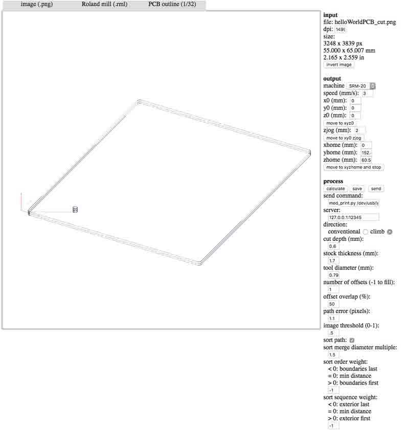
The board is ready to be cut; EAGLE's job is complete. Time to export. From the View> Layer settings... menu, set all the layers to invisible except Top, Pads and Dimension.
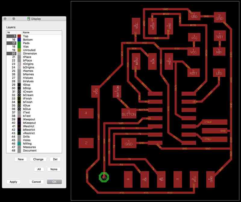
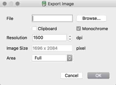
Export the file as a monochrome PNG at 1500 dpi.
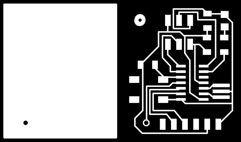
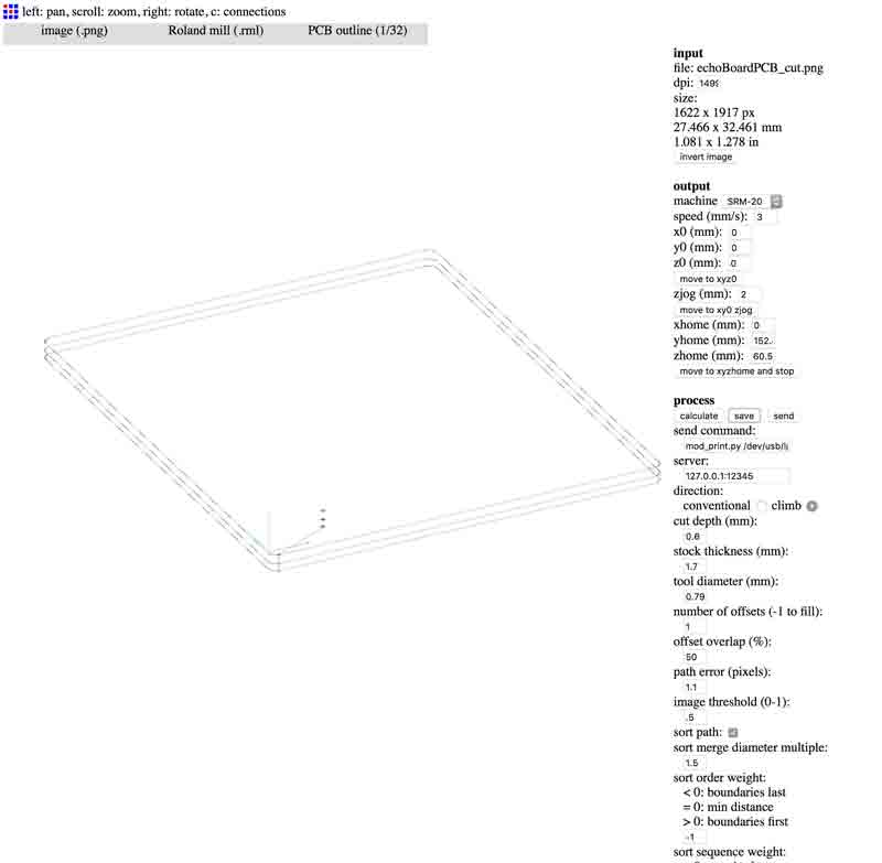
The PNG may not be exported in perfect condition but can quickly be edited in a PNG suitable editor, i.e. Photoshop, Inkscape. I did not find a good way to export a PNG for the outline cuts. EAGLE has a thin line it considers the outer border of the board and will export that line. The line, however, is too thin for Fab Modules. I deleted the line from the trace PNG and deleted the traces from a duplicate of the file to be used for the outline. I also slightly rounded the corners of the outline and added the eye graphic to the traces. Now the outline and trace files can be converted to tool paths in the Fab Modules.
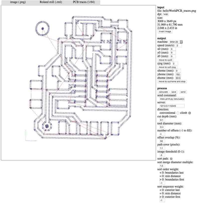
On final inspections prior to milling, thankfully, I discovered some mistakes. Double check the dimensions in the input information on the upper-right hand corner of the Fab Modules page. Above, you will see inconsistencies. For instance, my PNGs were nearly double the size drawn in EAGLE! I found Adobe Photoshop doubles the dimensions of the exported PNG upon opening. In pixels, the EAGLE output is: 1696x2084 and upon opening in Photoshop: 3398x4174.
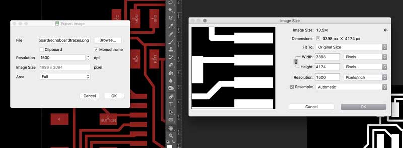
To solve the error, I scaled the PNGs in photoshop by 0.49928126. Fortunately, the image fidelity sustained. Next, I realized the outer dimensions of the trace and outline PNG files were dissimilar. This was my fault and would have resulted in an outline cut offset from the traces. I fixed the issue in Photoshop and took the exported PNGs back through Fab Modules.
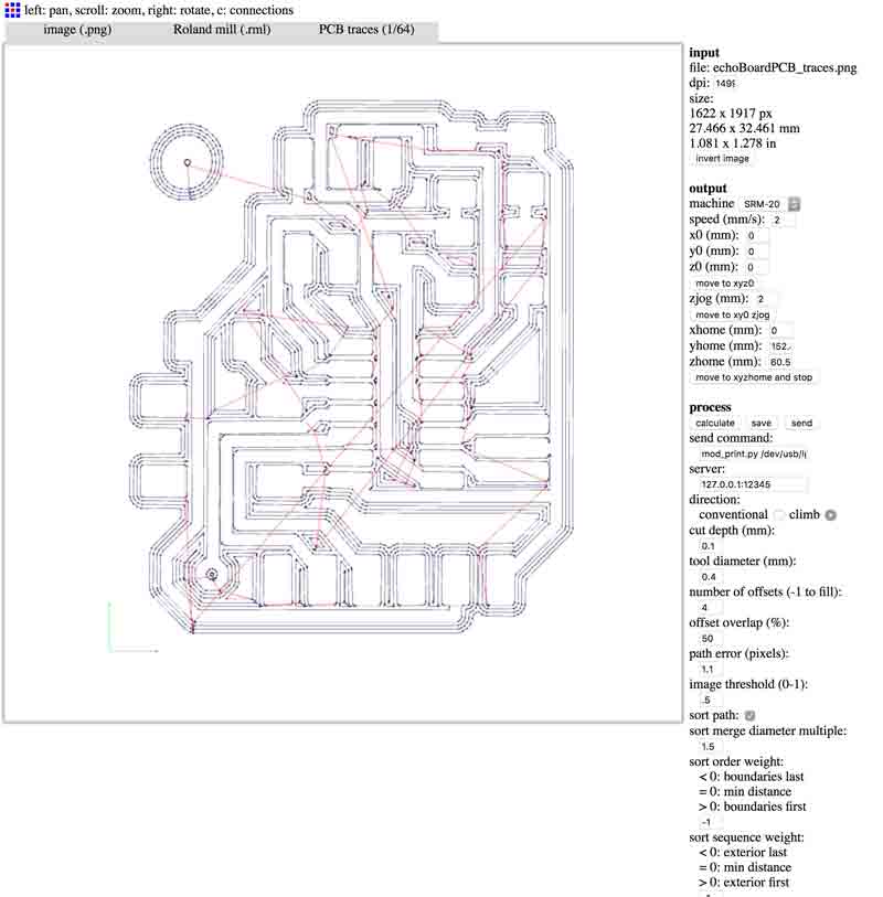
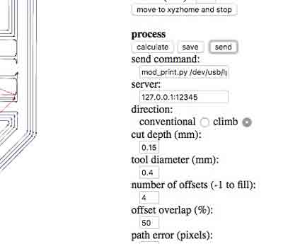
Now the input information is correct and the tool paths aligned. Check that the x0, y0, and z0 coordinates are correct. For me the coordinates were automatically changed to 10,10,10. After milling a bit, I noticed the paths around the traces were not cutting through the copper. We resolved either the bit is dulling or the substrate was not evenly adhered to the foam block.
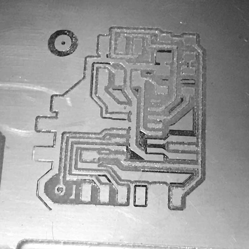
I paused the mill and added 0.05mm of depth to the trace cuts in Fab Modules. Without changing the XYZ origins, I loaded the modified tool paths into the CNC mill and recut on top of this flawed version.
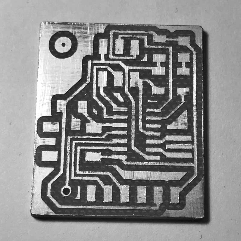
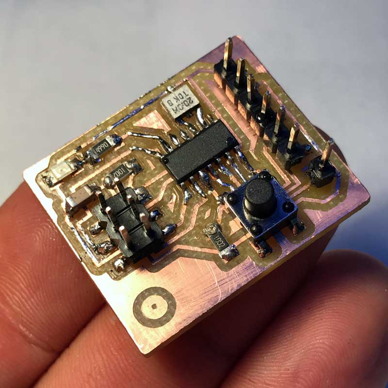
Problem solved. The mill has cut my PCB. The template I chose for the 1x1 pin header was for a size not stocked in the lab so the pad and hole were too small. I opened the hole with a drill press and resolved to solder along the trace.
Out lab only had through-hole buttons in stock so I bent and trimmed the pins. Further we did not have any 1x6 surface mount pin headers so I made a custom by pulling pins from a 2x and putting them into a 1x through-hole header. After soldering:
Download project files
Share this post...
« Previous post :: Fabricating, wiring, learning
This dance is as follows: mill, solder, wire. Familiar aesthetic for the board. Milling the traces at 0.10mm depth once again was unsuccessful so I dropped the depth to 0.15mm and milled on top of the previously milled stock. Soldering was significantly faster. This time, when heating the connections I kept a count in my head which varied from an one to three count according to the size of the components. Worked well in terms of pace. Checked all the connections with a multimeter. No problems. Initially I connected an incorrect resistor in front of the LED which took me...
Next post :: Prototyping the effector »
The effector pushes the brush into the drawing surface and pulls it away. Included in the mechanism is the flow of water from the reservoir into the brush tip. This design uses a 2BBYJ-48 stepper motor we had in stock in the lab. Precision of movement is not needed. In the design of the stage, I left some gaps that could be used to attach an effector shield. We also looked at an effector designed by Simone Boasso previously. With these starting points, I designed this: I created a larger guide for the vertical movement with a perpindicular axis for...